Other Parts Discussed in Thread: BQ25185
Tool/software:
Even if I disable the CE pin of the BQ25185, charging does not stop completely. Why is this?
Tool/software:
Even if I disable the CE pin of the BQ25185, charging does not stop completely. Why is this?
Hello Masaru,
Are you using a real battery or an electronic load on the BAT pin? If you're using an electronic load, I recommend placing a large (1000uF+) capacitor at the BAT and GND connectors in order to prevent oscillations at the BAT pin.
Please let me know if you still see this behavior after adding the cap.
Best regards,
Alec Lehman
Alecさん、ご返信ありがとうございます
。BATピンに2.35AhのLi-Ionバッテリーを接続しています。Li
-Ionバッテリーには充電状態を監視するガスゲージICが内蔵されており、バッテリーが80%充電されたらCEピンをHi(3.3V)にして充電を停止したいのですが、充電電流を完全に止めることができず、100~300mA程度の充電電流が流れ続けます。TS
/MR端子は10kでプルダウンして機能をキャンセルしています。
Thanks for your reply, Alec.
I have a 2.35Ah Li-Ion battery connected to the BAT pin.
The Li-Ion battery has a built-in gas gauge IC that monitors the charging status, and I would like to stop charging by setting the CE pin to Hi (3.3V) when the battery is 80% charged, but I cannot stop the charging current completely and a charging current of about 100 to 300mA continues to flow.
The TS/MR terminals are pulled down with 10k to cancel their functions.
Hello Masaru,
Thank you for clarifying the details of your system. Which path are you measuring this 100 to 300mA current on? Could you please confirm whether this is the charge current to the battery or the current to the system load? Specifically, is this current from VBUS to VSYS, VBUS to VBAT, or VBAT to VSYS?
Best regards,
Alec Lehman
Thank you for your support, Alec.
The 100 to 300 mA current after disabling CE is the current that flows from VBUS via the BAT terminal to the Li-Ion battery. This is information read via the I2C bus from the TI gas gauge IC built into the battery.
Charging does not stop even after disabling CE, and the charging current will reach zero when the battery is 100% charged.
Hello Ochi-san,
Best regards,
Alec Lehman


Thank you for your support, Alec.
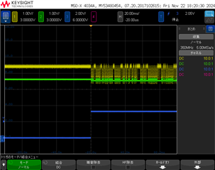
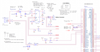
I am sending the circuit diagram and signal waveforms.
The signal waveforms are VSYS, VBAT, and CE from top to bottom.
VSYS becomes disrupted when CE changes from enabled to disabled.
Hello Ochi-san,
Thank you for providing the waveform and schematic.
I have seen this behavior before, and it is typically related to the amount of capacitance on VBAT and VSYS. We are currently investigating this issue further.
In the meantime, could you try adding more capacitance to the SYS and BAT pins to see if that fixes it? Additionally, what is your input source voltage and expected system load current?
Best regards,
Alec Lehman
Hi Alec.
Thanks for your advice.
When I replaced the 1uF capacitor attached to Vin with a 22uF, the oscillation-like phenomenon that occurred when disabling CE disappeared, and charging stopped.
When I enabled CE, charging began, and I was able to control charging via CE.
Thank you very much.
Hello Ochi-san,
I'm glad to hear that adding capacitance resolved the issue. If you have any other questions, please feel free to reach out.
Best regards,
Alec Lehman