This thread has been locked.

If you have a related question, please click the "Ask a related question" button in the top right corner. The newly created question will be automatically linked to this question.

LM1117: Output drift

Part Number: LM1117

Tool/software:

Hi sir

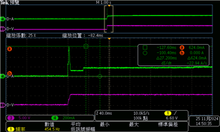
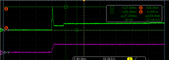
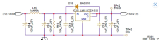
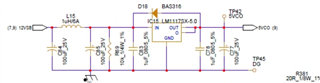
past few years. I use the LM1117SX-5.0 to be a power stage from 12v to 5v

now I found some device are drift ,some is 5.2~5.4V, 3.8V, 0V, that is incorrect

did  you have any advise?

thanks

  • Hello Alex,

    Are you saying that you are noticing 5.2~5.4V, 3.8V, 0V on the output for some of these devices instead of 5V?

    Has anything changed on the circuit boards? When was this problem first noticed? How many devices/ boards are affected (absolute as well as % of total)?

    While long term drift can cause a deviation from nominal Vout, the 3.8V and 0V observation would indicate something other than drift.

    Regards

    Ishaan

  • hi Ishaan

    yes,noticing 5.2~5.4V, 3.8V, 0V on the output for some of these devices instead of 5V?

    no any changed on the circuit boards.

    some data code have the issue. did you got same issue from other customer?

    ceramic cap or others comp result in the issue?

    thanks

  • Hi Ishaan

    today, we do the some test, when the chip out error as the 3.8V or OV, 

    move LM1117 from the PCB, and test it single. it's output correct 5v without any load

    if any passible, the LM1117 OCP on the PCB? so output drop down to 3.8v or 0v?

  • hi SIR

    Below chart is show the output of LM1117,

    in the case, the vin is 12v, Vout is 5v, current about 660mA peak

    the LM1117 Is suit for this case?

    thanks

  • Hello Alex,

    Sorry for the delay in getting back to you. We have been a bit stretched out during Thanksgiving break.

    Did you got same issue from other customer? ceramic cap or others comp result in the issue? - No. What is the ESR of your output capacitors. What type are they? Can you re-test after DNP C7 8 (the ceramic output capacitor)?

    if any passible, the LM1117 OCP on the PCB? so output drop down to 3.8v or 0v? - Could you please share scope shots and pictures of the test setup for this item? What is your Iout? The 0V case could be related to thermal shutdown but I need to know Iout to confirm that.

    in the case, the vin is 12v, Vout is 5v, current about 660mA peak the LM1117 Is suit for this case? - At this value of Iout, power dissipation in the LDO is 4.62W which would likely cause thermal shutdown. But this depends on package used, board layout and ambient temperature. What is the package you are using?

    Best regards

    Ishaan


  • Full part number is LM1117SX-5.0/NOPB 

    package as below

  • hi  sir 

    1: remove the ceramic output capacitor, LM1117 Still output 3.8v in some pcb 

    2.Green line is current waveform in back of the LM1117

    3.used package as below

  • Please share a picture of board layout as well as picture of assembled board. The schematic looks acceptable except for R69. What is the purpose of this resistor?