This thread has been locked.

If you have a related question, please click the "Ask a related question" button in the top right corner. The newly created question will be automatically linked to this question.

BQ25798: BQ25798 and BQ40Z50 precharging conflict

Part Number: BQ25798
Other Parts Discussed in Thread: BQ40Z50, , BQ40Z50-R2

Tool/software:

Hi there—our product comprises a 1S battery pack implemented using a BQ40Z50, and charged by the BQ25798. The pack implements its own precharge path—the schematic is identical to figure 9-1 of the BQ40Z50-R2 datasheet, modified according to the datasheet for a 1S design.

The precharge current-limiting resistor (R1) is 100 ohm, and the precharge threshold of the is BQ40Z50 is set to 2.5 V. The UVP threshold of the BQ40Z50 is set to 2.8 V, so we don't expect the precharge path of the BQ40Z50 to be enabled under normal circumstances. Stated another way, the battery should not self-discharge below 2.8 V within any reasonable time frame.

We received a customer return in which the cells had self-discharged to nearly 2.2 V, prompting the BQ40Z50 to enter precharge mode and enable its PCHG FET. This inexplicably low cell voltage suggests one or more cell(s) is defective, and the pack will go back to the vendor for FA.

Once I started charging the battery, I noted the BQ25798 repeatedly elicited a VBAT OVP fault; its registers were reported as follows:

     0  1  2  3  4  5  6  7  8  9  a  b  c  d  e  f
00: 04 01 90 01 f4 24 00 64 d4 0a 23 00 dc 4b 3d a2
10: 80 00 10 01 14 aa c0 7a 55 00 64 0f 0a 01 10 00
20: 20 00 00 80 10 10 20 00 ff c7 7f 1f ff fc 80 00
30: 00 00 c5 00 00 14 3c 14 44 14 42 0a 90 0f 2e 02
40: 59 00 28 00 00 00 00 00 19 ff ff ff ff ff ff ff

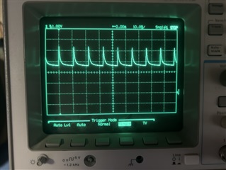
I measured cell voltage (2.2 V DC) on the cell side of the precharge current-limiting resistor, and the rapidly enabled and disabled charger output on the pack side of the precharge current-limiting resistor as follows:

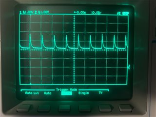
This is synonymous with the battery being disconnected, although it is not—it simply seems as though the charger cannot push current through the PCHG FET of the pack. I shorted across the precharge current-limiting resistor, and the OVP fault was removed. The same registers suggest the BQ25798 is successfully precharging the battery:

     0  1  2  3  4  5  6  7  8  9  a  b  c  d  e  f
00: 04 01 90 01 f4 24 00 64 d4 0a 23 00 dc 4b 3d a2
10: 80 00 10 01 14 aa c0 7a 55 00 64 0f 4a 01 10 00
20: 00 00 80 80 10 10 20 00 ff c7 7f 1f ff fc 80 00
30: 00 03 33 03 5f 13 e4 13 e3 13 e0 0a 88 0f 1d 02
40: 59 00 4d 00 00 00 00 00 19 ff ff ff ff ff ff ff

This loosely suggests the BQ25798 uses a constant-current source during precharging mode, presumably with weaker output impedance that cannot overcome the 100-ohm precharge current-limiting resistor. Is there any chance this is the case?

If so, do you recommend we bypass our pack's PCHG FET in favor of its heavy-duty CHG FET? If not, is there any other possible explanation for this behavior? Thank you in advance for your support—in case I can provide any additional information, please let me know.

  • Hi Jeff,

    The charger is pushing current through precharge resistor and that is causing the OVP since IPRE = 0.8A*100ohm + VCELL > VREG.  What is the voltage at the BATP pin when this occurs?  But you are correct in that the charge should have taken over precharge when battery drop below 74%*VREG and therefore never dropped to 2.8V.  The most common issue is too much SYS load current for the charger's input power, which requires supplement mode = battery drain.

    Regards,

    Jeff

  • Hi Jeff—thank you for your prompt support as always. In response to your feedback:

    The charger is pushing current through precharge resistor and that is causing the OVP since IPRE = 0.8A*100ohm + VCELL > VREG.

    Acknowledged on all counts—thank you for confirming.

    What is the voltage at the BATP pin when this occurs?

    This waveform is essentially the same as that of the pack side of the precharge current-limiting resistor, with the troughs raised by a diode drop:

    I think we're simply seeing the body diode of the DSG FET in the pack—once the converter briefly shuts off in response to OVP, any pack-side capacitance bleeds off into the battery until the body diode stops conducting.

    But you are correct in that the charge should have taken over precharge when battery drop below 74%*VREG and therefore never dropped to 2.8V.  The most common issue is too much SYS load current for the charger's input power, which requires supplement mode = battery drain.

    The charger seems to be operating as expected—once I short the precharge current-limiting resistor and alleviate the OVP fault, I see the cell voltage tick up to 2.3 V, 2.4 V, etc.

    The charger will indeed move to fast-charge mode eventually, but I'm manually disabling charging before this point. Because these cells are suspected to be defective, I'm purposefully avoiding moving too much charge in or out before the vendor has a chance to perform FA.

    The 2.8-V threshold I mentioned in my original message is unrelated. This is the UVP threshold of the BQ40Z50 as configured in our application—once the BQ40Z50 enables UVP, we don't expect the battery to self-discharge much further. The fact that I encountered batteries having self-discharged down to 2.2 V while the BQ40Z50 remains in UVP points to an issue in the pack itself, independent of the charger. We will dig into this phenomenon with our pack vendor.

    One last question for now—the BQ40Z50 has a firmware option to enable the heavy-duty CHG FET in precharge mode, effectively shorting the precharge current-limiting resistor responsible for this OVP fault. This will give the charger a low-impedance path to the battery under all conditions, leaving the charger as the sole arbiter of precharging. Does this workaround seem reasonable?

    On a related note—this topic could make for a handy application note, if one does not exist already. Unsuspecting customers may be tempted to use TI flagship devices in unison, both connected according to their respective datasheets. In cases such as this where both devices may offer precharge control or JEITA monitoring, the system designer must take care to avoid unintended behavior such as what we encountered here.

    Fortunately, both the gauge and charger are flexible enough that any of these scenarios can be easily resolved using register settings alone.

  • Hi Jeff,

    Disabling the BQ40's precharge should fix the issue.  I agree that we need a BQ40Z50 ref design and/or app note with BQ25798 and have proposed one.  But unfortunately, no one has the time to document it.    We have also had some customers disable BQ25798 termination and use the BQ40's charge FET to perform termination but, that does not work well the BQ25798, or any of our NVDC chargers.

    Regards,

    Jeff

  • Sounds great Jeff—thanks again for all of your help!