Tool/software:
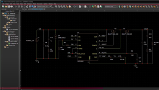
I am using Orcad PSpice to simulate ISO16750-2 transients in an LM74900-Q1 application circuit.
I wanted to import a txt file with voltage waveform from the ISO16750-2 4-6-4 Test A as a PWL source and apply it as an input voltage to the LM74900-Q1.
And then, do I need to add the internal resistor specified by the standard between the PWL voltage source and the A pin of LM74900-Q1?
If I didn't add it, the current flow from the PWL voltage source was not limited and the transient simulation result was not correct.
However, I am wondering whether this is the right way to simulate the internal resistance of the voltage source outside of the source.
Should I set the internal resistance on the PWL voltage source itself, and is there a way to do that?


