This thread has been locked.

If you have a related question, please click the "Ask a related question" button in the top right corner. The newly created question will be automatically linked to this question.

LMG2100R044: Schematic Validation/questions

Part Number: LMG2100R044

Tool/software:

Dear,

BLDC Motor control with 48V 15 Amps, please could you validate and comment this schematic : 

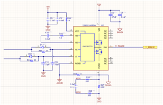
1) R15 needs to be 0 ohm or NetTie ?

2) C6 C7 are enough or need more capacitor ?

3) Do I need capacitor (100 nF)  between HB and HS direct ( I saw it on some schematic) ?

4) C8 and C9 refers to GND ?

Thanks

  • Hi,

    1. R15 can be 0 ohms or net tie, Agnd and Pgnd are connected internally inside the device. Outside of the device, they can be connected but we suggest keeping the ground planes separated near the device in order to keep noise from the Pgnd from affecting the Agnd.

    2. C6 & C7 decoupling capacitance will depend on your load current and the parasitic inductance from your source to the LMG2100 device. For the LMG2100R044 these values aren't too small to begin with, if there is too much voltage ringing on the switch node waveform then more capacitance can be added here.

    It is also important to place these as close as possible to the device as possible. Figure 8-7 in the datasheet gives a good example.

    3. The capacitor between HB-HS is the bootstrap capacitor, the way you have it placed in the schematic above is correct. The resistor in series allows for control of the slew rate.

    4. C8 & C9 should refer to Agnd. C11 & C12 should also refer to Agnd

    Best,

    Kyle Wolf