Because of the Thanksgiving holiday in the U.S., TI E2E™ design support forum responses may be delayed from November 25 through December 2. Thank you for your patience.

TPS2557: TPS2557 breaking

Part Number: TPS2557
Other Parts Discussed in Thread: TPS2552

Tool/software:

I have a circuit with a TPS2557 and a TPS3436BFACA. When I power it normally, it seems to work perfectly. However, when I bypass this circuit and apply 3.3V to the output (which I do for programming because I don't want the watchdog to interfere with programming), it seems like either the TPS2557 or TPS3436BFACA is breaking.
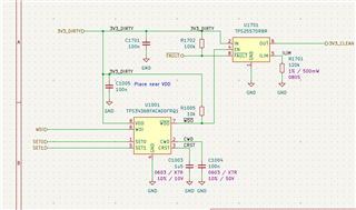
I am using the watchdog to control a power switch instead of connecting it to my microcontroller reset pin because I want to completely power cycle the entire board for my application.

When I say either the TPS2557 or TPS3436BFACA is breaking, I mean on some of my boards it seems like the TPS2557 is not working as specified and on others it seems like the TPS3436BFACA is not working as specified.

  • Board 1: WDO never goes high. Conclusion: Watchdog broken, switch unknown.
  • Board 2: Watchdog desoldered after strange behaviour noticed. WDO is always high (no watchdog chip to pull it down). The fault pin is high, but the switch output is low. Conclusion: Switch broken, watchdog unknown.
  • Board 3: Trace cut between watchdog and pullup resistor. Switch works. EN is always high and the switch outputs 3.3V. If I connect an external pull up resistor between 3.3V and WDO, it is pulled low. Conclusion: Watchdog broken, switch works.

In every case, the watchdog was working perfectly before applying the reverse voltage.

The TPS2557 does not have any reverse voltage protection (unlike the TPS2552). However, it's not that the switch is powered but a higher voltage is applied at the output. In my case, the switch is unpowered. I would expect the MOSFET to be non-conducting. I did not think it would hurt anything to apply a voltage at the output. In the absolute maximum ratings, it says voltage from IN to OUT can be -7V to 7V.

As long as I don't power WDI, SET0, or SET1 while the watchdog has no power, I think I am staying within the maximum ratings of each chip. Did I miss something? What could be the problem?

  • Hi Marcel,

    Can you clarify a few details for me?

    However, when I bypass this circuit and apply 3.3V to the output

    I assume you mean short TPS2557 IN (2) and OUT (6) pins.

    Board 2: Watchdog desoldered after strange behaviour noticed. WDO is always high (no watchdog chip to pull it down). The fault pin is high, but the switch output is low

    Are these scenarios separate from when you short IN and OUT?  Have you removed the short by this point?  Otherwise it doesn't make sense to me that the switch output is low, since it is externally driven.

    Otherwise I have no concerns with the voltages you are driving on the TPS2557 pins.

    Regards,
    Eric

  • Hi Eric,

    Thanks for your response.

    I assume you mean short TPS2557 IN (2) and OUT (6) pins.

    No. I mean instead of supplying power through the normal power connector (which supplies IN (2)), I supply power through the STLINK programming connector directly, which is connected to OUT (6). So OUT has 3.3V and IN is floating.

    Are these scenarios separate from when you short IN and OUT?  Have you removed the short by this point?  Otherwise it doesn't make sense to me that the switch output is low, since it is externally driven.

    Yes. This is separate from bypassing the switch (not exactly shorting IN and OUT as discussed above).

    The use-case is that I want to program the microcontroller without interference from the watchdog (I know I can disable it with set pins, but it's not convenient on the current version of my board). Therefore, for programming, I connect 3.3V directly to the STLINK connector, which is connected to OUT. After the MCU is programmed, I unplug the STLINK connector and supply 3.3V on the power input (IN). It's at this point that I get the strange behaviour.

    Regards,

    Marcel

  • Hi Marcel,

    Thank you for clarifying.  I don't see any issue from a TPS2557 perspective.  When you attach the STLINK and float the input side of the device, the voltage should be blocked by TPS2557.

    I ran a quick check on an EVM.  I supply 3.5 V to OUT while floating the input side pins.  Then I move the supply to IN, and everything works as expected (EN is pulled up, so OUT goes high, no FLT).

    What's on 3V3_CLEAN when you see the strange behavior?  Do you have any caps on this rail?

    Regards,
    Eric

  • Hi Eric,

    Thanks for your response.

    3V3_CLEAN powers a microcontroller. There is about 40uF of capacitance in total.

    I'm pretty sure I fried the watchdogs because I put voltage to the input pins while the device wasn't getting power. This goes against the absolute maximum rating of VDD+0.3. I will add some protection in the next revision of the circuit.

    However, I'm still stumped why the TPS2557 is breaking. I have at least 1 that seems broken to me (Board 2 from my first message).

    Regards,

    Marcel

  • Marcel,

    Understood.  I don't have any good suggestions at this point.  Is the issue repeatable at all?

    Thanks,
    Eric

  • Hi Eric,

    Unfortunately, I fried all 3 boards I had. I've just ordered a simple board specifically to test this with all the pins broken out to make it easier to test. I will try to test it methodically starting from the least likely thing to break it and document everything.

    Thanks,

    Marcel

  • Thanks Marcel.  Please update me if there is a repeatable fail.