Tool/software:
Hi,
I am using an Excel calculator to determine the constants of IC peripheral components. Please confirm whether my understanding is correct.
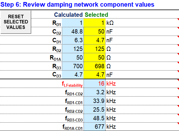
Q1. The source impedances estimation is difficult. Are there standard values on the calculator? In reality, I think it is necessary to adjust it based on the characteristics of the system and circuit, but can you give me some advice on the guideline value?
Q2. fLFstability (an index of low frequency stability) is an important factor for the stable operation of the design. TI's design guidelines state that the system may become unstable in the range of 10-100kHz. Is my understanding correct?
Also, if the above understanding is correct, when I entered the constants based on Step 6, fLFstability = 17.5kHz. What settings do I need to review to set fLFstability to 100kHz or more?
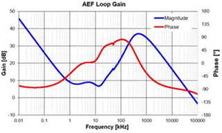
Q3.With what frequency should the calculated results of fLFstability, fRD1-CD2, fRD1-CD1, fRD2-CD2, fRD3-CD3, and fRD1A-CD1 be compared? Also, do they affect the AEF-Loop Gain?
Q4. In the waveform below, the high magnitude area shows that the filter is effectively reducing noise. Phase is an index for checking stability. In particular, a phase margin of 45° or more at the crossover frequency (the point where the gain is 0 dB) is a condition for stable operation. Is my understanding correct?
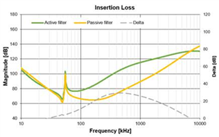
Q5. The frequency band where Magnitude (green line) is increasing is the area where the active filter suppresses noise more effectively than the passive filter. The larger the Delta (gray line), the greater the improvement effect. Is my understanding correct?
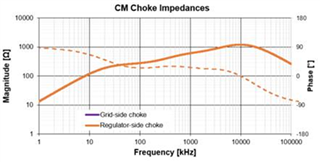
Q6. This graph analyzes the impedance characteristics of a common mode choke. The dashed line chart shows the phase characteristics, which indicates the phase change of impedance according to frequency. Also, there is no indication of the Grid-side choke, but it can be displayed by parameter input settings. Is my understanding correct?
Thanks,
Conor


