This thread has been locked.

If you have a related question, please click the "Ask a related question" button in the top right corner. The newly created question will be automatically linked to this question.

UCC28C58: UCC28C58

Part Number: UCC28C58

Tool/software:

Hello-

I am using UCC28C58QDRQ1 for a 2-level boost converter intented for solar application. The controller IC is powered from an independent 18V from a bench power supply for example. 

My question is regarding reverse current protection. If an operator mistakenly reverses polarity of HV power supply connectors (i.e.. connects DC+ to DC- and DC- to DC+), the body diode of MOSFET will conduct the reverse current. In this case, I would like to turn-on the n-channel of the MOSFET, so reverse current instead of flowing through the body diode flows through the n-channel. In this case, will the controller IC anyway operate at max. duty cycle of 99% or something and tunrs on the n-channel of MOSFET? Also, would be great if you can suggest other ways to implement this (turning on n-channel when reverse current flows though the body diode of MOSFET)

Couple of points to note here:

1. Since, this is intended for PV applications, in above scenario, reverse current will be limited. So, like a constant current application. So, there is no risk of damaging the MOSFET with a reverse polarity protection or need of an overcurrent circuit.

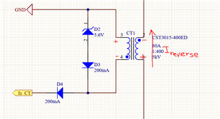
2. With UCC28C58QDRQ1, undernormal operation, current control is executed with a CT. D4 takes care that in case of reverse current through the MOSFET, no negative voltage is applied to controller IC, as if CS pin -0.3V, it can damage.

I can send schematics over a private message for the review.

  • Hi,

    Please provide the circuit you are referring and indicate how the polarities are reversed by indicating in that circuit. It is difficult to understand your description without the circuit so to avoid misinterpretation, you need to provide the circuit to help your description.

  • Hi, I have sent you the schematic and circuit description in a private message. Can you please check.

  • Hi,

    When current flow through Q3 body diode, this creates a -0.7V outside of -0.3V.

    What is D4 forward voltage drop? Is_CT will be negative and equals to D4 forward voltage drop, likely also outside -0.3V.

    The negative current also tries to flow from U1 pin 5 to any other pins so to create possible negative voltage outside of -0.3V, unless you add a Schottky from pin 5 to any pins of U1 to clamp the negative voltage within -0.3V, otherwise it does not seem you can limit each pin voltage within -0.3V. If +18V on VDD is from some other source, VDD pin should be ok. But other pins may not. VREF pin 8, is likely to superimpose a negative voltage, to change its voltage lower, then circuit inside the IC will be affected since all circuit inside also uses this same VREF to bias or to functions.

    It does not seem it can work like your expectation.

  • Hi, 

    When current flow through Q3 body diode, this creates a -0.7V - This is correct but that will not appear across the controller. Based on the dot convention of CT, when reverse current flows through body diode of Q3, D4 will be reverse biased and current will not flow in secondary of CT (Is_CT should not be -ve as no current flows as D4 is reverse biased), protecting the controller. The forward voltage drop of D4 is low, we can assume ~0.7V,

  • Hi,

    The voltage from DC- to DC+ will force D4 conduct to make CS voltage negative.

    I think you can make a simple test to find this with any similar circuit board to check. No matter what you still need to check to find if your thought how the reality is or what is the reality.

    I have made my point. If you do not agree, please make some test to check. If your test confirms your idea, then forget about mine and move on.

    Not much meaning to discuss again as you can move on with the test check results.