This thread has been locked.

If you have a related question, please click the "Ask a related question" button in the top right corner. The newly created question will be automatically linked to this question.

TPS3430-Q1: Watchdog random reset with external debugger

Part Number: TPS3430-Q1
Other Parts Discussed in Thread: TPS3430

Tool/software:

Hello

we are using this TPS3430 as windows watchdog with CYT2B74 MCU(5V), 

but whenever we connect the debugger/ winades tool at the JTAG_RESET  connector for debugging or data capture. Then the Randomly the WDO getting reset.

below you can see the schematic of watchdog section, here the JTAG_REST is connected to DAP connector, and RESET singal is connected to CYTB MCU reset pin.

with and without 120ohm same reset happens and also we tried by replacing the WDO pullup to 30K to make the current less than of 200uA, but still same issue.

2nd option we made little modification on the resistor connection like below, but still random reset happens at flashing or when connected the external tools on JTAG_REST


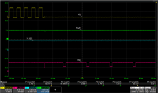
WDI we giving as 100Hz pulses 

as per datasheet data seems our design is within the watchdog boundary 

please look on the schematic and suggest what is wrong on it what to modify. 

Looking forward to your answer as its priority testing.

Thank you! 

  • Hi Praveen, 

    Thanks for your explanation. I will assist you with this issue. Schematic overall seems okay to me.  I just wan to first check what is the difference between two figures? They seemed the same to me and I don't want to assume/miss anything. 

    And could you please provide more information;

    1) What is the status of SET0 and SET1? is it always as in the schematic (Set 0 = 0 and SET1= 1)? 

    2) Oscilloscope picture that shows the WDI and WDO (when DAP connector is connected)? I suspect that WDI is not receiving a proper negative edge, potentially due to the DAP adapter, despite the MCU signal being sent on time. 

    Best,

    Sila 

  • Hi Sila,

    Thanks for the quick reply,

    sorry the 2nd image pasted wrongly (same as 1st) here we made small modification the JTAG_RESET signal line 

    25R8 instead of connecting it on 25TP5 , we removed 25R8 and connected with 25TP7(to see the pullup for external JTAG_REST line) but both option1,2 same resetting.

    and both options we modified the WDO pullup as 30K,20K, and recently 10K but still resetting.

    Below the required info:

    1) yes in this design we connected SET 0=0 and SET1=1 all the time as a hardware control.

    but provision is given to MCU pin for SET0, SET1 via 25R1, 25R5(not mounted) as not implemented sw now only HW control.

    and for rest issue below two cases we observed

    2) when we connecting external wire (thin copper wire for probing at WDI,WDO,5V supply line) or the tools( such as miniprog, winades,) in DAP connector the signal lines are disturbed and getting random reset- below you can refer the waveform taken at that time,

    Full waveform : 

    Zoomed in waveform:


    3) next when we connecting miniprog in DAP connector for flash. During flash some times it is getting reset (randomly 2 out of 5 times) you can see the waveform taken at the time of reset.

    Note : in waveform the label reset is at WDO line, 

    zoomed in waveform at the resetting duration: 

    Normal flashing without any reset issue waveform for your reference below:

    full waveform:

    Zoomed in waveform:

    • Info: if we isolate the watchdog section (by removing 680R series connection) from MCU board working fine after all external tools at DAP is working fine.

    please look into the points 3 &2  and comments us if any improvment to be done and let know if needed some more waveforms.

  • Hi Praveen, 

    Thanks for clarifying the difference and providing more information regarding this inquiry. I looked into your points #2 and #3. Please find my comment in below.

    2) It seems like the negative edge is not in the valid window. ( When CWD = NC, SET0 = 0, SET1 = 1)

    Please find the correct operation in below.

    3) In this waveform, the WFI signal is quicker. I noticed VDD is almost going to Vdd(min) for all the scope pictures. Is there anyway you can test with VDD signal is higher than VDD(min). Just want to make sure VDD is being close to Vmin is not disturbing anything. 

    Hope my feedback helps! Let me know if you need further assistance.

    Best Regards,

    Sila Atalar 

  • Hi Sila,

    Thanks for your reply,

    for point 3) yes the 5V(Vdd) is always dipping, 

    that is we expecting as issue,  on that period reset is triggering and 5V also drops.

    but if we isolate the watchdog from the board and if we continue the debug through DAP connector there was no issue and no 5V (Vdd drop).

    so it's seems the watchdog connection only causes this reset issue, As said above the schematic is done as per datasheet suggestion,  not clear what can be done further? 

    And one more doubt is it necessary to connect the SET 0, SET 1 pins to MCU instead of hardwire during the debug?  

  • Hi Praveen,

    You can connect SET 0 and SET 1 either to MCU or directly to VDD/Ground. There shouldn't be any difference for device behavior as long as they have the proper voltage low and high. 

    I want to highlight whenever the LIN_SLP_N signal goes low, it seems like the VDD and WDO output is having the issue. I want to check what is the purpose of LIN_SLP_N signal to better assist you. And is it a signal that you can stop toggling for only testing purposes? 


    I think the further step for debugging would be:

    Remove the DAP connector and and stop toggling the LIN_SLP_N signal, provide the proper WDI signal as in the second oscilloscope picture, and record the RESET behavior. I think this way we can understand the TPS3430 behavior. 

    And could you please let me know is this seen across multiple devices or only for this device? 

    Best,

    Sila