This thread has been locked.

If you have a related question, please click the "Ask a related question" button in the top right corner. The newly created question will be automatically linked to this question.

LM5148: LM5148 output coil makes noise and gets hot at idle

Part Number: LM5148

Tool/software:

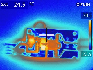
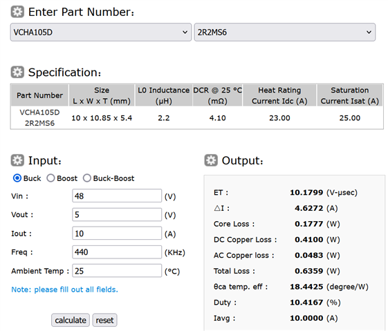
Hello, I am trying to make the 3rd design in the datasheet using LM5148. I have selected the components in the datasheet and set up the circuit, but the LM5148 and the Lout coil are slowly heating up and there is a sound in the Lout coil. Can you help?

  • Hi Talha,

    I have a couple of requests:

    1. Please fill in the quick start calculator for this device: https://www.ti.com/tool/download/LM5148-LM25148DESIGN-CALC and share with me? 

    2. Please share what is the operating condition of the device at which you are testing the system? (output current, output voltage, input voltage, etc).

    Thanks,

    Best Regards,

    Taru

  • LM5148_LM25148_quickstart_calculator_A4 (2).xlsm Elimden geldiğince doldurdum.

    Iout=8A

    Vout=5V

    Vin=50

  • Hi Talha,

    Few observations/ comments:

    1. There is a lot of ringing on the HO and LO nodes (The voltages on the LO switch node is -2V minimum and 6.8V max -  this exceeds the abs max ratings of the pin - which may lead to the device getting damaged). This maybe visible if the probing is not done well (I see a blurred capture on your oscilloscope - please ensure you capture the waveform correctly) or the layout needs improvement - the trace inductance on the path from the HO to the Gate of the MOSFET can lead to this ringing. Please refer to the layout suggestions mentioned in the datasheet.

    2. The device seems to be operating at  ~400kHz which is close to the programmed frequency. My initial guess is that the inductor maybe hitting saturation - can you share the Inductor part number with me? Inductor noise and heating at high loads is generally because of the inductor hitting saturation. If possible, you can cross check this by looking at the inductor waveform as well.  

    Thanks,

    Best Regards,

    Taru

  • inductor number: 74437368022 (Würth Electronic)

  • After some effort I managed to get it working. I replaced the output inductor with a 10uH and added a 100nF capacitor to the Cboot capacitor. The regulator works normally when idle, but when I start drawing current I hear a noise from the inductor and when the current reaches 3.2A it starts to heat up as seen in the image. I think it needs to be optimized more. Do you have any suggestions for optimizing it more?

  • Hi Talha,

    The boot cap should be 100nF, no need for higher as this needs to be charged by the VCC cap without discharging it too much. The quickstart file is incorrect, as Cout is not 188uF. Each 47uF ceramic cap will derate significantly at 5VDC (maybe to ~20uF each - check the cap datasheet for the derating curve with voltage). If I put Cout = 80uF in the quickstart attached, the recommended compensation values are 4.22kΩ, 10nF and 150pF.

    LM5148_LM25148_quickstart_calculator_A4 - 48Vin 5V 10Aout at 440kHz.xlsm

    Based on the attached quickstart, the ripple current is high at 47% with a 2.2uH and this will cause high core loss (check the Wurth loss tool). 10uH then is too high, causing low ripple current and very little ramp for current-mode control. I think 2.8-3.3uH is ideal here if you're using that Wurth series, giving 30-35% ripple current. Alternatively, use the Cyntec VCHA105D 2.2uH with these losses:

    https://www.cyntec.com/CoreLossCalculator.aspx?id=7

    Regards,

    Tim