This thread has been locked.

If you have a related question, please click the "Ask a related question" button in the top right corner. The newly created question will be automatically linked to this question.

TPS25750: Unrecognized MODE value

Part Number: TPS25750
Other Parts Discussed in Thread: TPS65987

Tool/software:

Hi there—we received an RMA in which the customer reported the device charged very slowly after the charger was inserted following a dead-battery condition.

During boot, our system firmware reads the MODE register of the TPS25750 (0x03) to ensure it matches one of 'APP ', 'BOOT' or 'PTCH'. Looking at the internal logs for this device, the MODE register returned something else in this particular instance. Our system firmware then assumed the TPS25750 was in an error state, and forwent loading a patch bundle. Charging was then limited to 5 V, which explains the customer symptom.

Unfortunately, our system firmware at the time did not log the actual return value of the MODE register, only that it did not match one of the three expected values. I set up an automated test that simulates charger insertion following a dead-battery condition, then checks that the TPS25750 was recognized by our system firmware.

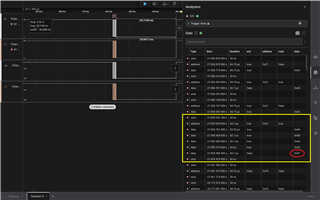
After roughly 5000 trials, I was able to reproduce this issue. In the failure case, the MODE register returned 0x04, 0x50, 0x54, 0xFF, 0xFF (P-T-ÿ-ÿ) instead of 0x04, 0x50, 0x54, 0x43, 0x48 (PTCH). I didn't have a logic analyzer connected at the time, but our logs show that the I2C controller indicated the read was successful.

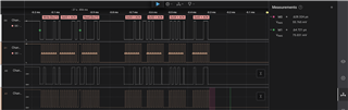
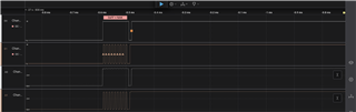
I suspect the TPS25750 went into a reset state after the read operation already started. With our I2C controller already having received an ACK and nothing to pull SDA low, our I2C controller simply saw the idle SDA line as all ones (0xFF) for the remaining length of the read operation.

My hypothesis is that a glitch on VBUS may have reset the TPS25750 while it was in dead-battery mode and bus powered. To protect against this scenario in the future, we have added a small retry loop to our system firmware. Only if the MODE register consistently returns an unrecognized value, or the read operation consistently fails, will the TPS25750 be assumed to be in an error state. My questions are as follows:

[1] What is the maximum time from VBUS first appearing, to when the TPS25750 can be accessed over I2C and the MODE register will return 'BOOT' or 'PTCH'? This start-up time will inform the delay of the retry loop.

[2] Are there any other explanations or known behaviors that may explain this issue? I found a thread in which a TPS65987 customer observed the byte count of registers read over I2C was correct (e.g. 0x04), but the data bytes also returned 0xFF.

Thank you in advance—in case I can provide any additional information, please let me know.

  • Hi Jeff, 

    [1] What is the maximum time from VBUS first appearing, to when the TPS25750 can be accessed over I2C and the MODE register will return 'BOOT' or 'PTCH'? This start-up time will inform the delay of the retry loop.

    Will look into this and get back to you with details. 

    [2] Are there any other explanations or known behaviors that may explain this issue? I found a thread in which a TPS65987 customer observed the byte count of registers read over I2C was correct (e.g. 0x04), but the data bytes also returned 0xFF.

    Since this issue is not easily replicable (you mentioned about 5000 trials) this may just be a corner case issue. At any point did TPS25750 lose power (either through VIN_3V3 or VBUS) when your MCU is reading the MODE register?

    Thanks and Regards,

    Raymond Lin

  • Hi Raymond—thank you for your prompt support as always.

    After another ~10,000 trials, I was able to reproduce this issue again; this time, I had a logic analyzer connected to the I2C bus that supports the TPS25750. It seems the issue happens when our processor briefly pauses in between bytes during the I2C read, as shown below:

    This scenario is uncommon, but it can happen if our processor services another high-priority interrupt for an extended period of time. By monitoring the subtle differences in the clock level, we can confirm that our processor is responsible for the delay, and not the TPS25750:

    After the next-to-last byte is returned, the TPS25750 clock stretches for less than 30 us; this is made apparent by the slightly lower amplitude of the clock (TPS25750 and processor driving in parallel).

    After that time, the TPS25750 releases the clock; the amplitude increases slightly as only our processor continues to hold the line while it waits to finish the I2C read. By that time, the TPS25750 stopped participating, and the final byte was seen as 0xFF by both our processor and the logic analyzer:

    The delay introduced by our processor between bytes is not ideal, but I expected the TPS25750 to return 0x48 and not 0xFF once our processor finally does drive the final 9 clock cycles. This implies the TPS25750 underwent some kind of reset condition, which leads me to my next question:

    [3] Some parts I've worked with in the past include an I2C watchdog that resets the device internally if the clock is idle too long in between start and stop conditions; is there any chance the TPS25750 includes a similar function?

    In response to your question:

    At any point did TPS25750 lose power (either through VIN_3V3 or VBUS) when your MCU is reading the MODE register?

    That's a great question—I need to disassemble the RMA further to gain access to these signals, so I've been avoiding this step so as to not disturb its original state. Based on your feedback for [3], I can try this next.

    Thanks again for your continued support—in case I can clarify any of my observations, please let me know.

  • Hi Jeff, 

    Some parts I've worked with in the past include an I2C watchdog that resets the device internally if the clock is idle too long in between start and stop conditions; is there any chance the TPS25750 includes a similar function?

    We do have a watchdog timer in TPS25750, let me dig into the specifics more. 

    Your explanation/observation is clear on my end, I'll get back to you once I have more details on TPS25750 error recovery/timer on its I2Cs lines. 

    Thanks and Regards,

    Raymond Lin

  • Hi Jeff, 

    The I2C timeout for TPS25750 on its I2Cs pins is set to roughly 175ms, however this applies for if the TPS25750 is holding the clock line low and not the other way around. Since the processor stopped reading the MODE halfway through, it's possible TPS25750 needed to clear the I2C buffer and cleared it. Still looking in the specifics of this specific corner case.

    Thanks and Regards,

    Raymond Lin

  • Hi Raymond—Happy New Year! Thank you for the update; please keep me posted.

  • Hi Jeff, 

    Confirmed with team, if there is abnormal behavior on the I2C lines TPS25750 has an internal timer of ~175ms. If the EC needs to go process something else in the middle of the read-back, it's recommended to add a STOP bit, when TPS25750 receives a STOP bit it'll hold onto the remaining data and wait until the I2C master comes back and finish the remaining task. Otherwise without the STOP bit, TPS25750 will clear the data once the timer expires and the EC will either need to re-read the MODE register again or used whatever data it was able to receive previously.

    Let us know if you have any further questions or concerns! 

    Thanks and Regards,
    Raymond Lin

  • Hi Raymond—thank you for the update. Please forgive me, but I have a couple remaining questions just to ensure we have indeed found the root cause:

    [1] Are the values I've reported (0xFF) representative of the TPS25750 clearing its outbound data buffer as a result of the 175-ms timeout? If the buffer was merely cleared, I would have expected the TPS25750 to actively drive 0x00.

    Due to the nature of the open-drain bus, it's impossible to tell whether the TPS25750 intends to send 0xFF, or simply became unresponsive immediately after acknowledging the address byte.

    [2] This phenomenon occurs for a pause as low as 25 ms; it is significantly below 175 ms. Are there any conditions during which the timeout may vary from 175 ms? Maybe it's lower during PTCH mode, then overridden by an updated patch bundle during APP mode?

    Thanks again for your continued support—in case I can clarify either of my questions, please let me know.

  • Hi Jeff, 

    [1] Are the values I've reported (0xFF) representative of the TPS25750 clearing its outbound data buffer as a result of the 175-ms timeout? If the buffer was merely cleared, I would have expected the TPS25750 to actively drive 0x00.

    I'll need to double check with the team and see if the buffer is typically filled with 0xFF or 0x00 in this scenario. The buffer may just be filled with random data if the timeout did occur or some other case. 

    [2] This phenomenon occurs for a pause as low as 25 ms; it is significantly below 175 ms. Are there any conditions during which the timeout may vary from 175 ms? Maybe it's lower during PTCH mode, then overridden by an updated patch bundle during APP mode?

    The 175ms timeout applies for APP mode, for PTCH mode I'll need to double check and see if the timeout changes. 

    Thanks and Regards,
    Raymond Lin

  • Hi Raymond—thanks again for your continued support! Look forward to your feedback.

    In the meantime, I have implemented a workaround that retries the read to the MODE register a finite number of times in case one or more unexpected bytes are returned. After several days of continuous testing, the problem reproduced; I am happy to report that the second read (with no delay between bytes) was successful.

    I think the last step now is just to confirm that the characteristics of the TPS25750 watchdog match my observation; then we can close this thread. In case I can provide any additional information, please let me know.

  • Hi Jeff, 

    1. There isn't a clear answer as to what the buffer could be, since the read was stopped halfway through it could out the buffer in an abnormal spot causing it to be filled with 0xFF. 

    2. In PTCH mode the timeout is set to around 25ms, in APP mode you should see the timeout closer to 175ms. 

    Let me know if there are any additional questions or concerns! 

    Thanks and Regards,

    Raymond Lin

  • Hi Raymond—thank you for the update; this confirms that my observation matches the design of the IC, and there are no remaining mysteries. Thanks again for your help throughout this issue; have a great weekend!