This thread has been locked.

If you have a related question, please click the "Ask a related question" button in the top right corner. The newly created question will be automatically linked to this question.

BQ25170EVM: Lithium Battery Protection using a BQ2980

Part Number: BQ25170EVM
Other Parts Discussed in Thread: BQ25170, BQ2980

Tool/software:

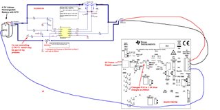
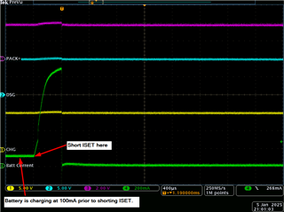
I have both the BQ25170 EVM and the BQ2980EVM now in my possession.  Per your comment, I did change the current sense resistor on the 2980 EVM to 90mOhm which went smooth so I don't think this is causing me problems.  I am running into odd behavior.  I have a rechargeable lithium that has a thermistor in it so it is a 3 wire battery consisting of Batt+, Batt-, and TS(thermistor).  Let me tell you the scenario that works.  I am using a power supply set at 5V  to power up the BQ25170 charger board (J1).  When I connect my lithium to the BQ25170 as follows:  Battery+ to J2 Out (Bat+), Battery- to J2 GND(Bat-) and the TS to J2 TS, the battery charger works fine.  My battery is charging at 200 mA because I have ISET at 1.5K.  This is expected operation.  Also, there are 2 leds on the BQ25170, PG and STAT  and both are on solid green.  

Now, when I add in the BQ2980 EVM things no longer work.  The green STAT led on the charger EVM blinks at a 1 Hz rate indicating a fault.  Let me explain my connection.  
   BQ25170 EVM                   BQ2980EVM       Battery (Lithium Rechargeable)
      J2 Out Bat+   ---------->      J1 Pack+
      J2 Gnd Bat -  ---------->      J1 Pack-
      J2 TS             --------------------------------------> TS
                                                 J2 Bat+   --------> Battery+
                                                 J2 Bat-    --------> Battery-
If my connection information isn't clear, I can try to draw a diagram of the connection to help.  Long story short, when I connect the battery to the charger EVM directly, it charges fine.  When I add the BQ2980 between the battery and the charger, the STAT light blinks at a 1 Hz rate and the battery will not charge.
Thank you
Diane
  • Hello Diane,

    I don't believe this is an issue with the BQ25170 device, it seems that the BQ2980 is hitting one of the protection thresholds. Can you share what the battery voltage is? is the CTR pin held low or high?

    Sincerely,

    Wyatt Keller

  • Hello Diane,

    A diagram would definitely be useful!

    Do you have any waveforms of the CHG/DSG pin of the BQ298x when attaching the charger? 

    Best Regards,

    Luis Hernandez Salomon

  • Thank you for your reply.  I attached a diagram of my connections between the battery and the two eval boards I have.  Your comment about CTR may be the issue.  You can see from the diagram and it not being controlled.  We really don't want to control it with the processor.  We want this to be totally a hardware solution.  When the battery goes over current (>200mA) or over voltage (>4.2V) we want the protection device to shut the charging off and it is only resettable by way of a full power cycle of the board.  You mentioned CHG/DSG waveforms.  I don't have any, but I can capture any signals you feel would help.  But, I believe CTR could be my issue since I currently have it just floating as my diagram shows.

  • Hello Diane,

    The engineer is currently Out of Office for today and tomorrow. They will be back Monday to provide a response.

    Thank you for your patience.

    Best Regards,
    Alexis

  • Hello Diane,

    As a quick test, you could try shorting CTR to VSS on the EVM. Just to rule out that it is causing any problems.

    Yes, if you could get waveforms of CHG and DSG while connecting the charger, that'd be good! Both of the pins should be high. If you remove the charger, does the part recover from the faulty state?

    Best Regards,

    Luis Hernandez Salomon

  • Hello Luis,

    I figured out a couple of things.  First of all, my charger was set to charge at 200mA and my BQ2980 eval board was set to protect an overcurrent at 200mA, so that is why the charger was faulting because the 2 values were the same so it was always in fault.  To confirm this, I set ISET on the BQ25170 eval board to 100mA and now my carger no longer faults.  I can continue to test with this and further characterize this part, but I have some questions.

    1.  Above I was told to put a 90mOhm Rsense on the BQ2980 eval module to trip at 200mA.  I'm a little confused on how this is arrived at, but let me tell you my opinion, then please correct me.  Table 4 (Device Comparison Table) shows OCC of -8mV for the BQ298000 which that part number is confusing to me.  The BQ2980EVM shows the part number in the BOM (Table 3) to be U2 = BQ2980RUG, but Table 4 (Device Comparison Table) doesn't show that part number, so I am confused there on the part number.  Moving on, 7.3.3 Overcurrent in Charge (OCC) Status says "The device detects an OCC fault when (VCS – VSS) < OCC".  I think OCC is -8mV, then if I use Ohms law where I want to trip at 0.2A, I solve for a resistance, but I don't come up with 90mOhm.  So, please describe your equation.

    2.  Last question for the moment, Table 4 (Device Comparison Table) shows BQ298218 with an OVP of 4.2V.  I need 4.2V, so I "assume" that is the part number I need.  Now, confusing to me is the column CTR/ PTC Config that showsPTC 5MΩ Pullup Enabled and that is different from all the rest of the parts.  I really don't want to use a PTC if I can help it.

    Anyway, again, thank you for all the help and I look forward to your answers.

    Diane

  • Hi,

    The engineer will be out for winter holidays until the New Year.

    Thank you for your patience.

  • Hello Diane,

    I think OCC is -8mV, then if I use Ohms law where I want to trip at 0.2A, I solve for a resistance, but I don't come up with 90mOhm.  So, please describe your equation.

    You would be correct. If OCC is -8mV, then using Ohm's law, you'd do -8mV/200mA = 40-mOhm. I am not sure why it seems like the EVM is different, I believe it should be BQ298000 on the EVM. Could you test what is the OVP for the device? To see if maybe it matches another device from Table 4?

    2.  Last question for the moment, Table 4 (Device Comparison Table) shows BQ298218 with an OVP of 4.2V.  I need 4.2V, so I "assume" that is the part number I need.  Now, confusing to me is the column CTR/ PTC Config that showsPTC 5MΩ Pullup Enabled and that is different from all the rest of the parts.  I really don't want to use a PTC if I can help it.

    You do not need to use a PTC if not desired. You can have a fixed resistor value instead, such as a 10-kOhm. Then the pin will not affect functionality. 

    Best Regards,

    Luis Hernandez Salomon

  • Hi Luis,

    I have a snapshot for you.  Things look pretty good.  Let me explain it, but I have labeled the traces as you can see.  The green is a current probe, TCP0030A clamped on the lithium red wire.  The purple trace is my PACK+.  You can see that when I short ISET, the current goes through the roof, but then goes to 0 within 400usec, so I think that is good.  The PACK+ rises momentarily and then goes back to normal.  What confuses me is why CHG and DSG remain high through this event.  Can you comment on that.  I need to buy an RSENSE that will allow me to charge at 200mA.  As you see, I had to change my charging current because my RSENSE was set to trip at 200mA so that would always trip which isn't good.  Let me know what you think about the trace and I'll get some parts ordered.

  • Hello Diane,

    About ISET, I assume you mean the charger. If CHG/DSG are both high, then I assume that the charger itself triggered a protections.

    Best Regards,

    Luis Hernandez Salomon

  • I have a new snapshot that looks good.  Here, I am shorting the charger IN and OUT which is a CSA test.  YOu can see prior to the shorting, the battery is charging at 200mA as it should.  I see the current and voltage spike, but then DSG and CHG go low which shuts the system down in about 8 msec or so which seems acceptable to me.

    The voltage does go to about 4.57V (I was using peak mode on my fluke voltmeter), but then it drops back to normal as you see.  Our battery is rated for 4.2V, but I hope this would be acceptable since it drops quickly.  I'm still confused on part numbers.  On the evaluation board, the BOM says the part number is BQ2980RUG, but that is not a valid part number in Digikey.  Can you explain.

  • Hello Diane,

    Yes that looks good to me. 4.57-V should be okay as long as it is less than the OVP delay, so I have no concerns there.

    I agree on the EVM, the BQ2980RUG on the BOM was likely a mistake by the engineer who originally made this board. The IC on the EVM board should be BQ298000RUG if it was correctly done.

    Best Regards,

    Luis Hernandez Salomon