This thread has been locked.

If you have a related question, please click the "Ask a related question" button in the top right corner. The newly created question will be automatically linked to this question.

TPS25750: TPS25750 + BQ25792 Charging with USB A devices

Part Number: TPS25750
Other Parts Discussed in Thread: TPS25751

Tool/software:

I have a design based on the above components. There is an MCU writing the binary to the TPS25750 on boot. When using USB C to USB C charging, both standard USB C charging and PD charging work as expected. 

When plugging in USB A devices however, the current is always ~400-500mA of draw, indicating no USB A charge profiling is occurring. This is true regardless of the five or so different USB A ports I have tried, with current outputs advertised in the 1-2.4A range. 

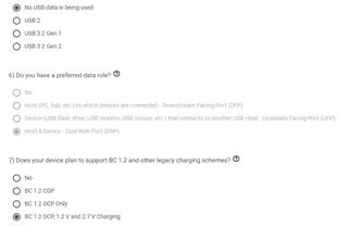
I believe I have the app configured correctly for the TPS to determine advertised current draw from USB A devices: 

I have the D+ and D- lines connected directly to the TPS25750's GPIO4+GPIO5 pins from the USB C port. There was ESD protection on these pins, that I have removed, but the effect still remains.

Any advice?

Thanks

  • Hi Jesse, 

    Thank you for reaching out!

    Could you please provide the json used? 

    Also, do you have scope captures of the behavior?

    Best Regards, 

    Aya Khedr 

  • Hi Aya,

    Yes here is the config JSON. I have tried both the 'old' and 'new' online config tool.

    The site is not letting me attach files, so I have pasted it below. Thanks:

    """

    {
    "questionnaire": {
    "device": "TPS25750",
    "toolBuildVersion": "1.0.2",
    "answers": [
    null,
    4,
    4,
    1,
    1,
    0,
    3,
    3,
    1,
    1,
    0,
    8.4,
    2.3,
    0.04,
    0.04
    ],
    "vendorId": "0000",
    "productId": "0000",
    "version": "1.0.0.2"
    },
    "configuration": {
    "data": {
    "selected_ace": [
    {
    "register": 6,
    "data": [
    0,
    0,
    0,
    0,
    0,
    0,
    0,
    0
    ]
    },
    {
    "register": 22,
    "data": [
    10,
    48,
    48,
    77,
    0,
    0,
    0,
    0,
    0,
    0,
    3
    ]
    },
    {
    "register": 50,
    "data": [
    0,
    168,
    42,
    44,
    145,
    1,
    38,
    44,
    209,
    2,
    0,
    44,
    177,
    4,
    0,
    244,
    65,
    6,
    0,
    0,
    0,
    0,
    0,
    0,
    0,
    0,
    0,
    0,
    0,
    0,
    0
    ]
    },
    {
    "register": 51,
    "data": [
    2,
    44,
    145,
    1,
    16,
    44,
    209,
    2,
    0,
    44,
    177,
    4,
    0,
    244,
    65,
    6,
    0,
    69,
    65,
    6,
    0,
    0,
    0,
    0,
    0,
    0,
    0,
    0,
    0
    ]
    },
    {
    "register": 92,
    "data": [
    49,
    0,
    0,
    0,
    0,
    0,
    0,
    0,
    0,
    16,
    0,
    0,
    0,
    0,
    0,
    0,
    48,
    0,
    0,
    0,
    0,
    0,
    0,
    0,
    0,
    12,
    0,
    0,
    0,
    0,
    0,
    0,
    0,
    0,
    0,
    0,
    1,
    0,
    0,
    0,
    0,
    0,
    0,
    0,
    0,
    0,
    0,
    0,
    0
    ]
    },
    {
    "register": 117,
    "data": [
    0,
    0,
    0,
    0
    ]
    }
    ]
    }
    }
    }

    """

  • Hi Jesse, 

    Thank you for providing. I will review and get back to you with feedback by Wednesday.

    Best Regards, 

    Aya Khedr

  • Hi Aya, we have some results on the TPS to BQ I2C initialization on startup.

    The order of registers being written to the BQ from the TPS, are below:

    0x10 REG10_Charger_Control_1 0x80
    -(0)Set WATCHDOG to Disable
    -(0)Set WD_RST to Normal(default)
    -(0)Set VAC_OVP to 26V
    -(2)Set VBUS_BACKUP to 80%*VINDPM (default)
    0x14 REG14_Charger_Control_5  0x1C
    -(0)Set EN_BATOC to Disable (default)
    -(0)Set EN_EXTILM to Disable external ILIM_HIZ pin input regulation
    -(1)Set EN_IINDPM to Enable (default)
    -(3)Set IBAT_REG to Disable (default)
    -(0)Set EN_IBAT to Disable IBAT discharge sensing at battery only (default)
    -(0)reserved
    -(0)Set SFET_PRESENT to NO ship FET populated
    0x11 REG11_Charger_Control_2 0x00
    -(0)Set SDRV_DLY to 'Add 10s delay time (default)'
    -(0)Set SDRV_CTRL to IDLE (default)
    -(0)Set HVDCP_EN to Disable HVDCP handshake (default)
    -(0)Set EN_9V to Disable 9V mode in HVDCP (default)
    -(0)Set EN_12V to Disable 12V mode in HVDCP (default)
    -(0)Set AUTO_INDENT_EN to Disalbe D+/- detection when VBUS is plugged-in
    -(0)Set FORCE_INDET to Do NOT force D+/- detection (default)
    0x12 REG12_Charger_Control_3 0x00
    -(0)Set DIS_FWD_OOA to Enable (default)
    -(0)Set DIS_OTG_OOA to Enable (default)
    -(0)Set DIS_LDO to  Enable (default)
    -(0)Set WKUP_DLY to 1s (default)
    -(0)Set PFM_FWD_DIS to  Enable (default)
    -(0)Set PFM_OTG_DIS to  Enable (default)
    -(0)Set EN_OTG to Disable OTG (default)
    -(0)Set DIS_ACDRV to Disabled (default)
    0x08 REG08_Precharge_Control 0x04
    -(0)Set VBAT_LOWV to 15%*VREG
    -(4)Set IPRECHG to 160mA
    0x09 REG09_Termination_Control 0x01
    -(1)Set ITERM to 40mA
    0x01 REG01_Charge_Voltage_Limit 0x0348
    -Set Battery Voltage Limit to 8400mV
    0x03 REG03_Charge_Current_Limit 0x00E6
    -Set Charge Current Limit to 2300mA

    Thanks

    Jesse

  • Hi Jesse, 

    Thank you for providing.

    I may need additional time to look into this. I will get back to you by the end of the week. Thank you in advance.  

    Best Regards, 

    Aya Khedr

  • Hi Jesse, 

    Thank you for your patience. 

    We are recommending the TPS25751 for all new designs. There are a couple of know issues found in the TPS25750 that are addressed in the TPS25751 specifically with the PD + battery charger pairing. Please see the following FAQ for more information.

    Best Regards, 

    Aya Khedr