This thread has been locked.

If you have a related question, please click the "Ask a related question" button in the top right corner. The newly created question will be automatically linked to this question.

ADCIN1 & 2 Voltage setup

Part Number: TPS25751

Tool/software:

Hello,

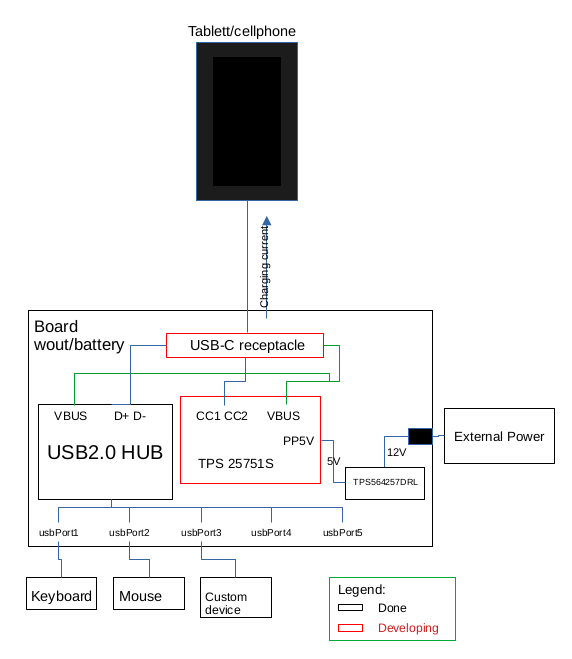
I'll use this chip to provide power to tablet/cellphone while using usb devices at same time like describes next schematic:

To reach that function I'll connect to ADCIN1 to LDO_1V5 (code 5) and ADCIN2 to LDO_3V3 (code 7) using table 8-6 of datasheet.

That's correct?

Thanks!

  • Do you have eeprom for 25751 FW? Does this device only operate then 12v supply is available?

  • Hi Ghouse,

    Do you have eeprom for 25751 FW?

    .-No.

    Another guy of TI support offer me 25751 like the solution for my case. Yesterday, when start to make a board and reading more details about 25751, see on datasheet that isn't clear to offer PD to tablet. After that see in your site offer a tooling that could inject firmware for different case of use.

    Won't to use FW as possible because turn complex the production. Want the chip, that manage CC lines, always offer to be the power source but not in mode dedicate charge port because the tablet will "not see" devices connected to usb hub.

    Does this device only operate then 12v supply is available?

    .-Yes.

    Thanks!

  • Hi Daniel,

    A firmware image must be loaded to the PD controller from an external source on boot of the device.

    There are two options here:

    1. Image is stored on an EEPROM attached over I2C, PD controller boots from EERPOM

    2. External MCU/EC obtains fw image and loads it to PD controller over I2C at boot.

    One of the two options is required to use this product.

    The tooling on the site (the App Config GUI) is used to generate said FW image and can load it to the EVM, but in reality it is loading the image to the EEPROM on the EVM. There is no way to use the tool to directly program the PD controller with the image.

    Won't to use FW as possible because turn complex the production. Want the chip, that manage CC lines, always offer to be the power source but not in mode dedicate charge port because the tablet will "not see" devices connected to usb hub.

    You must use FW, and one of the two options is required if using the TPS25751. I'm not too sure what you mean by the second sentence.

    Does this device only operate then 12v supply is available?

    Not necessarily. Ghouse is trying to determine how you are powering your system. The PD controller has the capability to be booted from the USB-C port and/or System power(the 12-V in this case). We want to understand if you want the Tablet/Cellphone to ever be a power sink and power the system.

    Thanks and Regards,

    Chris

  • Hi Chris,

    I'm not too sure what you mean by the second sentence.

    Tryed to explain to Ghouse that my case of use, need works like power source but not like dedicate power charger source where isn't possible use DP DM because need USB hub must be recognized by tablet and devices connected in the hub at same time.

    We want to understand if you want the Tablet/Cellphone to ever be a power sink and power the system.

    Tablet all time get power from the board, the board all time provide power to tablet.

    If I unplug external power source the tablet no turns as power source.

    Could exist other kind of chip that no need firmware?

    I hope that explain my best.

    Thanks!

  • Hi Daniel,

    Tryed to explain to Ghouse that my case of use, need works like power source but not like dedicate power charger source where isn't possible use DP DM because need USB hub must be recognized by tablet and devices connected in the hub at same time.

    I'm still not sure what you mean here.

    You want the USB-C port to be a power source, but you don't want it to be a dedicated power charging source? What is the difference between a power source and a dedicated power charging source? When you say use DP DM, do you mean in place of USB-C PD over the CC lines? The TPS25751 is capable of acting as a source for both PD and Type-C (non-pd) connections. There is a requirement for specific terminations on the CC lines for non-PD connections though.

    Tablet all time get power from the board, the board all time provide power to tablet.

    Understood, so the port should be source only, no sink. This can be configured through the GUI.

    Could exist other kind of chip that no need firmware?

    TI currently does not have a USB-C PD Source only chip that does not require the loading of this FW config from an EEPROM or MCU/EC as mentioned in the first response. If using the TPS25751, you will need to use one or the other. If using the EEPROM, you do not need to create the FW yourself. Instead, you use the online GUI to set your device configuration, and then generate the FW image file that can be loaded to the EEPROM.

    Thanks and Regards,

    Chris