This thread has been locked.

If you have a related question, please click the "Ask a related question" button in the top right corner. The newly created question will be automatically linked to this question.

BQ25792: No charge current

Part Number: BQ25792

Tool/software:

Dear TI Engineer,

We encountered some technical issues with debugging the BQ25792, the details are as below:

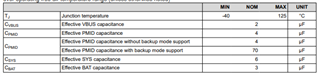
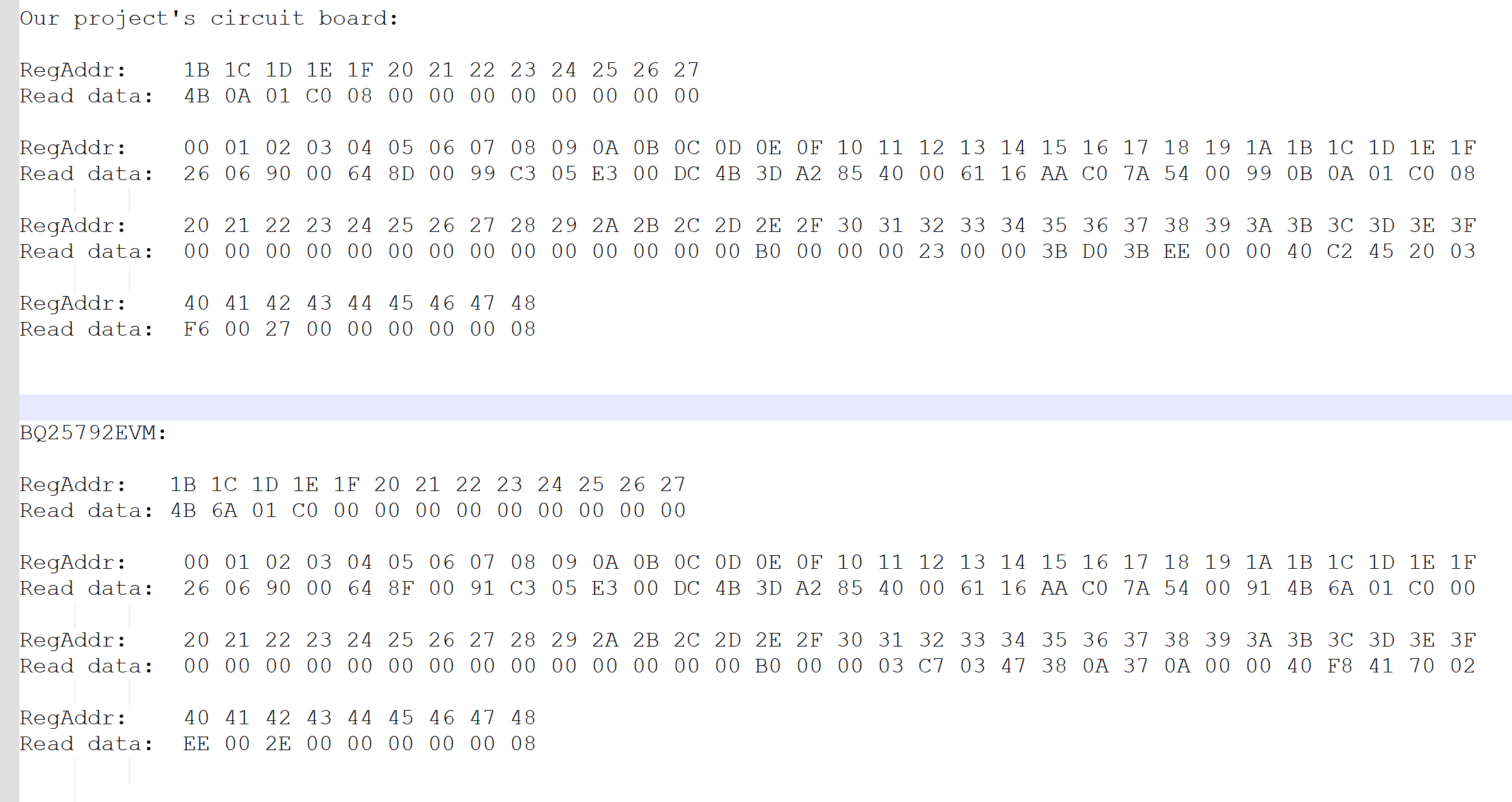
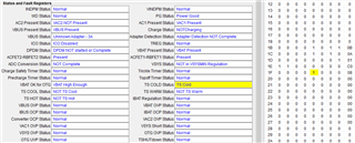
1) On the board we designed, when the input power is plugging in, the current is very low (only a few tens of mA). We have set the 0x03 (REG03_Charge_Current Limit) register to 0x0050, but the data read from the battery current register 0x33 (REG33_SBAT_SDC) is almost zero. The reading of battery voltage register 0x3B (REG33B_VBAT_SDC) is normal.

2) On BQ25792EVM, set the same parameters in the register, the charging current is normal, and reading the data from register 0x33 (REG33_SBAT_ADC) is also normal.

We have designed two input power, the logic is as follows:

1) If it is detected that register 0x1B bit2 AC2_PRESENT_STAT=1, we will enable the bit7: EN-ACDRV2 of 0x13h register,  and the bit5: EN_SBAT of  0x14h register. Set register 0x03h=0x0050, register 0x2Eh=0xB0, register 0x2Fh=0x00, register 0x30h=0x00;

2) If it is detected that register 0x1B bit2 AC1_PRESENT_STAT=1, it will enable the bit6: EN-ACDRV1 of 0x13h register, and the bit5: EN_SBAT 0x14h register. Set register 0x03h=0x0050, register 0x2Eh=0xB0, register 0x2Fh=0x00, register 0x30h=0x00;

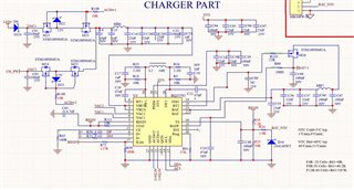
Below is the relevant registers setting and hardware design schematics. Can you help analyze the cause of the problem?

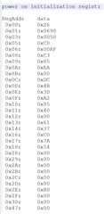
The register setting:
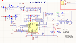
The schematic:

Thanks,

Kind Regards

  • Hi Lumina,

    I see a few schematic issues.  The main issue is no capacitors on SYS.   PMID and SYS are the input and output to the converter so those must have minimum capacitor after derating for applied voltage and temp per below:

    You might be able to move some of the VBUS capacitors to SYS if their voltage rating is high enough for 4S pack.  Please keep in mind that ceramic capacitors derate significantly with applied voltage.

    Also, the cap on VREG after derating for applied 5V needs to be 1uF.  If that 2.2uF is 16V rated or higher, it might derate no lower than 1uF but if lower, probably not.  Although probably not an issue, the BTSTx caps that will recommend are 47nF not 100nF and the additional 47nF on SDRV is not needed.  But for 4S, we recommend a 47nF on BATP if a fully charged battery will be hot plugged.

    Regarding the register settings, I don't see any issues except for fsw=750kHz and inductor = 1uH.  We only support inductor =2.2uH with fsw=2.2uH.  Also the watchdog timer is set to 40s so any charge related registers revert to default settings after 40s.  Lastly, there is no need to write EN_ACDRx =1 after reading the ACx Present bit because the charger automatically does that.

    Regards,

    Jeff

  • Hi Jeff,

    There is no system load need, we just using the BQ25792 to charge the battery, so we floating the SYS.Is this feasible?

    The main issue is no capacitors on SYS.

    Following your suggestion, we have redesigned the circuit as follows:

    On the new PCBA, we have measured that the SYS pin has output current, but the BAT still has no current output.

    Thanks,

    Kind Regards

  • Hi Lumina,

    What do the status and fault registers from REG0x1B to REG0x27 report?

    Regards,

    Jeff

  • Hi Jeff,

    The rgisters setting of BQ25792EVM and our own PCBA is as below:

    Thanks,

    Kind Regards

  • HI Lumina,

    The charger is in TS cold.  What is the voltage TS pin?  Is a thermistor connected?  If not, use the host to set REG0x18[0]=1  or change TS pin resistors to equal values to disable TS pin function.

    Regards,

    Jeff