This thread has been locked.

If you have a related question, please click the "Ask a related question" button in the top right corner. The newly created question will be automatically linked to this question.

TLV61220: Input current is unstable

Part Number: TLV61220
Other Parts Discussed in Thread: TPS61299, TPS61099, TPS61070

Tool/software:

Hello,

I am using a TLV61220DBVR in circuit and am having problems with input current instability.

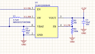
Vin = 1.4V, Vo = 3.3V, Io = 25mA max. AA lithium battery (1.3V-1.5V) to boost to 3.3V. The load is a regulated laser module that draws 20mA typ. Using a bench supply for input for this testing.

I have two units of my prototype assembled and running them under the same conditions, Unit 1 looks like the left and Unit 2 looks like the right (yellow is Vout, pink is input current, ground loop isn't amazing, ignore the noise on yellow):


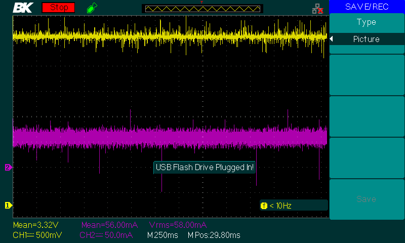
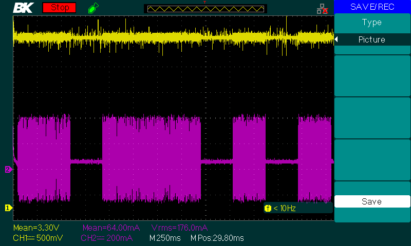
and zoomed in on the oscillation:

The output regulates with a ~200mVpp ripple, and the current ripple is showing 600mApp is much greater and has this irregular pulse behavior where it seems to be switching modes. It also audibly buzzes during the oscillations.

I also turned the input voltage on unit 1 down to Vin = 1.2V and it begins to exhibit the same behavior as unit 2 at Vin = 1.4V. Turning Vin down further did not keep it from intermittently switching modes like it is.

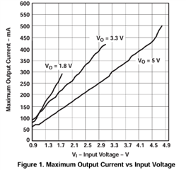
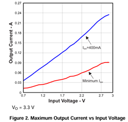
I am aware of the below curve in the datasheet. I am a little close, but at 1.4V I should be able to get at least 30mA it looks like (I need 20, 25mA max). This would probably explain it but I'm not sure why one unit would do it at 1.2V and one at 1.4V. I need this to operate at at least Vin = 1.4V because the efficiency goes way down if the input current is oscillating like that. The laser load works fine throughout, but I don't want to drain the battery faster than I need to.

Schematic

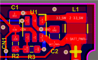
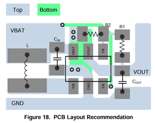
I have followed the layout recommendation in the datasheet exactly (after failing to do that the first rev and having even more problems)

I've tried upping the inductance and that doesn't seem to help anything. Inductor: NRH3012T4R7MN

Is there something I'm missing or I should try next to investigate? I've been trying to figure this out a while.

  • Hi Gage,

    the current limit is pretty at  the edge, Could you switch to device with higher current limit ? Such as TPS61099 or TPS61299?

  • It does seem to be pretty on the edge. The reason I am doing this design right now is due to a component obsolescence, and I selected this component due to several viable pin-compatible substitutes in case something went wrong down the line. I also preferred for assembly to not have DFN components or anything smaller than necessary. A TI chip that is pin compatible seems to be TPS61070 but I have now substituted that one in directly and it also has unstable input current and is audible, which actually gets more pronounced when inputting a higher voltage such as Vin = 2.0V. The curve on this one is much higher, so what gives?


  • Hi 

    Do you need true shutdown?

    could we discuss more about the project requirement and we could  communicate by e-mail.

    nini-zhong@ti.com

  • So it seems that the chip in question got damaged somehow. I replaced it and this erratic behavior stopped, and it matched the behavior of the "good" unit.

    As a very likely contributing factor to the poor looking input current ripple, I had too many feet of cable from the bench supply to the board, which could have made the input voltage locally unsteady. I shortened the clip leads powering the units by a few feet and the input current ripple is now reduced beneath the noise floor of my probe (as opposed to 50 to 100s of mA). I am remembering a line in the datasheet now "If the input supply is located more than a few inches from the device, additional bulk capacitance may be required in addition to the ceramic bypass capacitors. An electrolytic or tantalum capacitor with a value of 47 µF is a typical choice." So yeah, I made a setup error. The battery of the device is immediately next to the supply so this will not be a problem for the design.

    I am now getting proper performance of >75% efficiency at down to 1.2V in now with no suspicious input current ripple, which is sufficient for my design.

  • Hi Jeffrey,

    we are defining new device. Please help to communicate by e-mail.