Other Parts Discussed in Thread: TPS25750, BQ25731, TPS51397A
Tool/software:
Hi Ti Team
The following is my question about TPS25751:
- I want use TPS25751 to replace TPS25750, can it be directly replaced according to the reference design in the datasheet without additional changes to the circuit design?
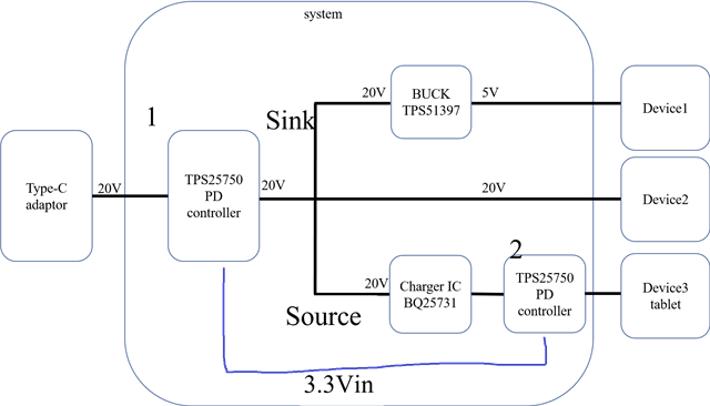
- If I use TPS25751, I only need to connect two components in the circuit to directly control the Charger IC BQ25731?
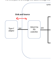
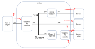
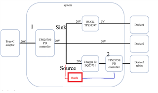
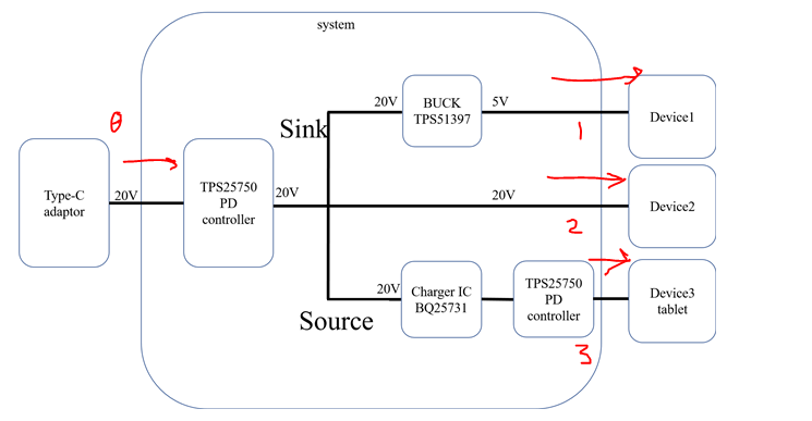
- If I use TPS25751 for source, should I use a charger IC for power management?If I use a charger with a PD controller, will the voltage output to the tablet be based on the PD protocol or be based on the charger voltage (1S~5S)?
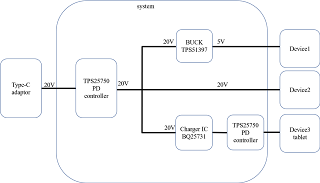
- My system requires one-to-three charging. The input voltage is 20V, and one of the outputs is 5V. Do I need a Buck circuit in this output path to reduce the voltage to 5V? Or can the voltage reduction be completed through the charger IC on the device side?
I look forward to hearing from you. Thanks a lot.