Other Parts Discussed in Thread: TL431, TLA431
Tool/software:
Hi Teams,
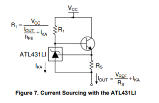
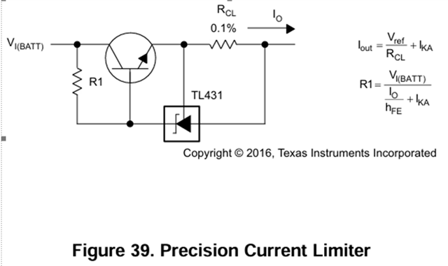
The customer built a circuit according to the application circuit in the TL431 manual, as shown in the following figure,
They want to confirm three questions:
1. Is Iout in Formula 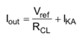 the same parameter as Io above
 the arrow?
2.If the input voltage VI (BATTA) is an unstable voltage value, such as varying between 9~32V, how should the resistance of R1 be determined? If the resistance values of R1 and RCL are both fixed, what is the output current of the circuit when the input voltage VI (BATT) varies between 9~32V? Is it constant?
3.Is this circuit a constant current source circuit? Or is it just a current limiter circuit? We want to use this application circuit to achieve a constant current output of 25mA. After reading some information, it is said that this is a constant current source circuit. The voltage between TL431 VREF and the anode pin is fixed, and a resistor can be connected in series between these two pins to output a constant current. For example, the RCL resistance is 100 Ω, Iout is 25mA, and according to the formula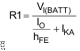 , R1 is 100k Ω when the input voltage VI (BATT) is 24V. When the input voltage VI (BATT) changes (between 9~32V), will the Iout current be affected because the R1 resistance is fixed?