This thread has been locked.

If you have a related question, please click the "Ask a related question" button in the top right corner. The newly created question will be automatically linked to this question.

REF102: REF102

Part Number: REF102
Other Parts Discussed in Thread: REF50, REF50E, OPA2156, LM317, TPS7B7702, TPS7B85-Q1

Tool/software:

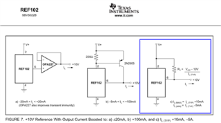
I am looking for a precision voltage source, 10V fixed output, 200mA current capability.

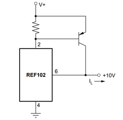
Is the REF102 a good choice for that application ? I am referring to the picture below taken from the part data  sheet.

Can you help indicating the complete circuit to be added to REF102 in order to boost the current accordingly?

Or, suggest another circuit that can do the job.

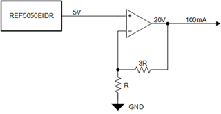
Further, we need a circuit with 20V fixed output, 100mA current.

Thank you for the help.

  • Hello,

    For 200mA output current, you could use a variation of any of these three options if you correctly choose components (i.e. op amp, transistor, resistor, etc.) for the current rating that you desire. I would recommend option A or option B because then you don't have resistor tolerance concerns that would be present in option C that could degrade accuracy performance further. For a 10V fixed output, REF102 is a good choice, or REF5010IDGKR (REF50) is also another good choice. 

    For 20V output, you would need to increase the output voltage using an op amp. For this, I would recommend REF5050EIDR (REF50E) with an op amp which can provide the required accuracy and also source 100mA of current in a 4x gain configuration on the output of REF5050EIDR.

    Information on REF5050EIDR: https://www.ti.com/product/REF50E 

    Out of curiosity, what is this voltage being used for?

    Thanks,

    Jackson

  • Thanks Jackson for the reply.

    I believe that example in Figure b is the more recommended for extensive current capability.

    In the meantime we found the part from MICREL MIC5158 for additional features that would work for us: uses external MOSFET for high current, Sense Resistor for monitoring the load current, Flag Indicator for a fault condition.

    Can you please recommend a similar part from TI?

    The application is for supplying a Wheatstone bridge with high precision 10V and then with 20V.

    The bridge is 350 OHM impedance.

  • Hello,

    With the right transistor, you are correct that figure B can likely source more current. What is your accuracy target? This will be helpful in recommending the best device.

    Thanks,

    Jackson

  • Good morning,

    The objective is to achieve 0.1% accuracy.

    0.5% accuracy would be still acceptable.

    Thank you

  • Hello,

    Here are my two proposals to obtain this level of accuracy with the voltage and current requirements you have provided:

    1. 10V 200mA Reference Voltage

    2. 20V 100mA Reference Voltage (Op Amp suggestion: OPA2156)

    To achieve your accuracy goal, I would suggest using a series voltage reference over an LDO like the MIC5158. REF102BU and REF5050EIDR have an initial accuracy of 0.025%. This is very accurate, and leaves more room for resistor tolerances and temperature drift in your 0.1% to 0.5% error budget than an LDO would.

    While LDOs do not reach the level of accuracy that REF102 and REF50E can, if you prefer to use an LDO at the sacrifice of lower accuracy, please let me know and we can provide some other options similar to MIC5158 as well.

    Thanks,

    Jackson

  • Thanks Jackson for the further help.

    The preferred solution should be in a configuration similar to the MIC 5158, with the accessible features that I listed about this part: external MOSFET for high current, Sense Resistor for monitoring the load current, Flag Indicator for a fault condition.

    Even though the LDO does not have the highest accuracy, we can select the external components/resistors to contribute to the overall circuit accuracy.

  • Hello,

    I will loop in the LDO experts to comment on the best suggestion similar to MIC5158.

    Thanks,

    Jackson

  • Thanks for the good help so far.

  • Hi,

    We do not have a part with a dedicated pin to gate voltage like the MIC5158. (There is technically way to wire a BJT across an LDO to amplify the current which maintains regulation because of the LDOs negative feedback, but I haven't seen it used beyond the LM317 nor adapted to a MOSFET). Typically, we just recommend a part with a higher current limit for higher current applications.

    I was able to identify a part promoted for high accuracy with fault indicator and current sense pins:

    TPS7B7701-Q1

    Datasheet: TPS7B770x-Q1, Automotive, Single- and Dual-Channel Antenna LDO With Current Sense datasheet (Rev. C)

    Output Accuracy: 2% (same as bandgap), current sense and error fault indicator pins, input up to 40V, max current 340mA-550mA which should be sufficient.

    Best,

    Gregory Thompson

  • Thanks Greg for the helpful info.

    I can see this part as a great solution; I also appreciate the dual LDO controller on chip feature for the TPS7B7702.

    I would believe that the part is suitable for our application Resistive Wheatstone bridge, which is different than the Antenna application described in the part Data sheet.

  • Glad we could find a suitable part.

    Antenna LDOs can be used for non-antenna applications (it's more of an intended/promoted application than a requirement), so it should work for your Resistive Wheatstone bridge.

  • Thanks again for confirmation.

    I will suggest this part for the new design.

  • I just received a response about this design idea, asking us to produce a better accuracy: 1% or better.

    Would it be possible to achieve this accuracy based on the TPS7B7702 circuit ?

  • Unfortunately, I don't think it's achievable with the TPS7B7702/1 because we're limited by the accuracy of the internal bandgap reference. Tracking LDOs use an external reference (which would just move the problem to another device), everything else is limited by the accuracy of the internal reference. 

    We do have a number of other LDOs that may work but nothing with both a current sense and error flag (power-good equivalent)

    Note: error indicator and power-good have equivalent operation

    We don't have a part with every feature you're looking for, but I was able to identify every part that was off by one feature. Note that, the TPS7B7702 is the only one with dual output.

    Issue GPN Accuracy Current Limit Error/Power Good Current Sense Pin
    Accuracy too bad TPS7B7702-Q1 2% 350mA-550mA Yes Yes
    Current Limit too low TPS7B85-Q1 0.75% 150mA Yes Yes
    No Current Sense TPS7B86-Q1 0.85% 500mA Yes No
    No Current Sense TPS7A26 1% 500mA Yes No
    No Current Sense TPS7A25 1% 300mA Yes No
  • I am wondering if the solution for increased accuracy can come from a configuration with an external precision reference and the controller with the known features.

    Can you please suggest such a combination from TI?

  • Unfortunately, we do not have a tracking LDO (the ones which target an external voltage) that could fit within your requirements

    The closest I could find was TPS7B4261-Q1 Automotive, 300mA, 40V, Voltage Tracking LDO With PG datasheet but it has no current sense pin.

    If it were applicable, I would suggest any of our high accuracy LDOs for the external reference since the tracking LDO gets around the current limit. 

  • This regulator has an excellent performance, but I will still have to check if we can around the missing current sense feature.

    Also, it appears that the Output voltage can only be equal or below the (external) Reference voltage, see below.

    I was considering a ref. voltage of around 5V and still be able to generate 20V at the output.

    Can you please check and confirm if this is accurate ?

  • It is accurate, output voltage can only be equal or below the (external) Reference voltage. Our tracking LDOs simply match OUT to ADJ, you can't generate a 20V output off a 5V reference passively, you would need some sort of amplifier to make it 20VADJ before the device.

    Current sensing would require an external chip if it doesn't have one integrated. The basic idea is that you would place a small resistor right at the output and measure the voltage change from there. If you place it before the feedback resistors if won't affect regulation. We do have chips specifically for that, but I'm not particularly familiar with our product offering there so I would have to redirect you to current sensing.

    You could also wire two TPS7B85-Q1's in parallel to get around the current limit issue, it works fine but you'd have to add values from both current sensing pins on your end.

    Parallel LDO Architecture Design Using Ballast Resistors

  • Thank you for confirming that.

    Yes, I would like to consider the option with Current sense feature; that I imagine can be implemented with a current sense resistor and a comparator that collects the voltage across it.

  • The INA 190 should work for that then. The current sense resistor can be placed before the input capacitor.

    INA190 Bidirectional, Low-Power, Zero-Drift, Wide Dynamic Range, Precision Current-Sense Amplifier With Enable datasheet (Rev. D)

  • Thank you very much; we now have enough data to go ahead with the decision.