


Other Parts Discussed in Thread: TPS62441-Q1, TPS6521905, TPS6593-Q1
Tool/software:
Application detail:
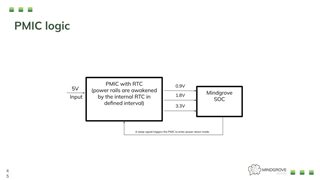
We are looking for a Power Management Integrated Circuit (PMIC) that can provide 3.3V, 1.8V, and 0.9V outputs. This PMIC must include an internal Real-Time Clock (RTC) to manage the power-up sequence of its outputs. To power down the PMIC, our System-on-Chip (SoC) will assert a 1.8V signal to the TPS650250.
For any queries feel free to contact us.
Links: Comparison Product
TPS65910 - How to wake up the platform / SoC using RTC_PERIOD_IT / INT_TIMER.
Please find the simplified block diagram in the attachment.
Kindly suggest a suitable Dual Buck converters TPS62441-Q1.
Note : Following PMIC / Dual Buck Converter going to incorporate in Mindgrove EVAL Board/ ASIC Boards/ SOM.
Note : Following PMIC / Dual Buck Converter going to incorporate in Mindgrove EVAL Board/ ASIC Boards/ SOM.
With Best Regards
Ismail P
System Engineer
Mindgrove Technologies
8015751791.