This thread has been locked.

If you have a related question, please click the "Ask a related question" button in the top right corner. The newly created question will be automatically linked to this question.

UCC28C59-Q1: UCC28C59-Q1 multi output flyback design

Part Number: UCC28C59-Q1
Other Parts Discussed in Thread: UCC28C59, UCC28C57H-Q1, , UCC28C57H

Tool/software:

Hello, I am planning to design a multi-output flyback converter with the following parameters:

System Parameters

  • Input Voltage: 250V ~ 800V

  • Output Power: 49W

Output Voltages and Currents

  • 5V @ 0.8A

  • 24V @ 1.2A

  • 15V @ 0.3A

  • -15V @ 0.3A

  • Switching Frequency: 40kHz ~ 100kHz

When using the TI Power Designer tool, I was able to design the converter with a single output.
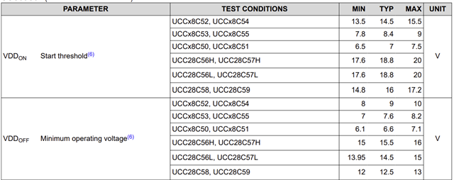
Would the UCC28C59 be an appropriate choice for this system configuration?
The MOSFET I intend to use is a SiC MOSFET, and most test conditions specify Vgs = 18V.


  • Hi,

    Based Vgs = 18V, it looks like UCC28C57H-Q1 should be used. Yes it is ok to use UCC28C57H-Q1 to achieve your specs.

  • Thank you for your response.

    Since the UVLO enable voltage of the UCC28C57H-Q1 is 18.8V, wouldn't it be more appropriate to use the UCC28C59H instead?

  • Hi,

    If you want to drive SiC MOSFET at 18V then UCC28C57H-Q1 is a match. UCC28C59 UVLO off is 12.5V, so you need to check if this is ok for your SiC.

    UCC28C57H-Q1 UVLO off 15.5V so safer to 18V SiC than UCC28C59-Q1.

  • Thank you for your response.
    As far as I understand, if the input voltage does not exceed the UVLO threshold, the IC power will not turn on. Is there anything I might be missing here? If Vgs is driven at 18V, I believe the UCC28C57H IC would not be properly enabled.

  • Hi,

    UCC28C59 starts to drive when VDD > 14.8V from some units, and after start can keep drive when VDD as low as 12V. Considering your SiC Vgs = 18V, it is at risk to damage when VDD < 18V, unless you have circuit to make VDD on and off more ch closer to 18V. 

    UCC28C57H VDD is in the range of 15V to 17.6V with worst turn on 20V which a SiC is ok to sustain. So UCC28C57H is better to use.

    You can provide your SiC datasheet for us to review to see if ok to use with which device.

  • Thank you for your response.

    Below is the datasheet of the SiC MOSFET.

    In this case, could you advise what VDD voltage would be appropriate if I supply VDD power through the auxiliary winding?


    Also, I’m still not fully confident that I understand the UVLO (Under Voltage Lock Out) function correctly, so I’d like to ask a few more questions — sorry for asking again.

    1. From my understanding, the problem seems to occur when the VDD voltage supplied is much lower than 18V. Would this also be a problem when designing the transformer’s auxiliary winding?

    2. According to the UCC28C57H IC datasheet, the VDDon is specified as 17.6V ~ 20V. Does this mean that this is the appropriate voltage range for VDDon to turn on? Or does it mean that the IC will only operate normally within this voltage range? I initially thought this voltage range was required for normal IC operation, so I assumed that if the VDD voltage was below 20V, the IC would not turn on.


    [B2M600170H] datasheet.pdf

  • I understand what you mean now. Thank you.

    I realized I had been thinking about it the wrong way. The correct operation is that the start-up resistor initially charges Vdd to exceed the UVLO on threshold. After that, when the IC starts operating and consumes power, Vdd drops, and then the auxiliary winding takes over to maintain the Vdd voltage. And from that point on, the IC turns off when Vdd falls below the UVLO off threshold due to the hysteresis.

    Thank you for the clarification.