This thread has been locked.

If you have a related question, please click the "Ask a related question" button in the top right corner. The newly created question will be automatically linked to this question.

LM5168: unable to carry the load

Part Number: LM5168
Other Parts Discussed in Thread: LM5163

Tool/software:

Hi team,

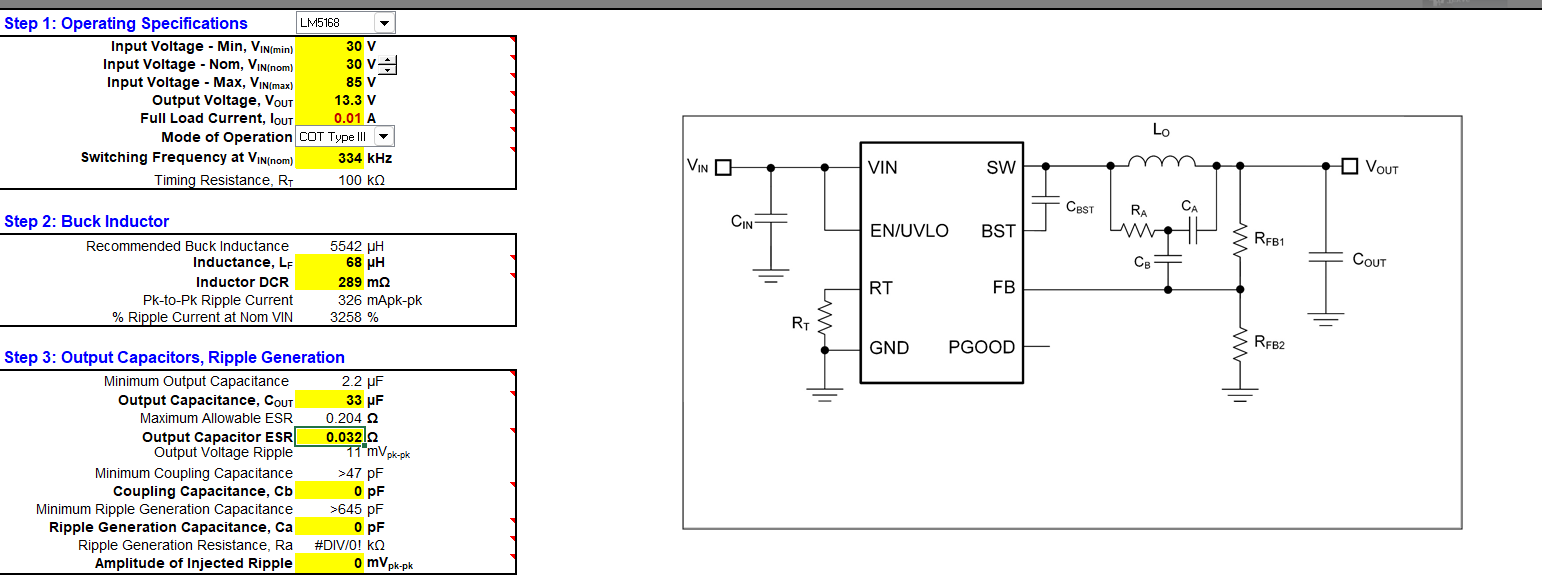
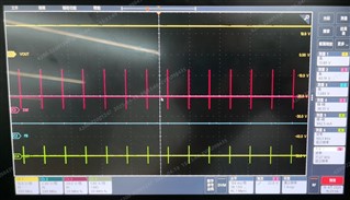
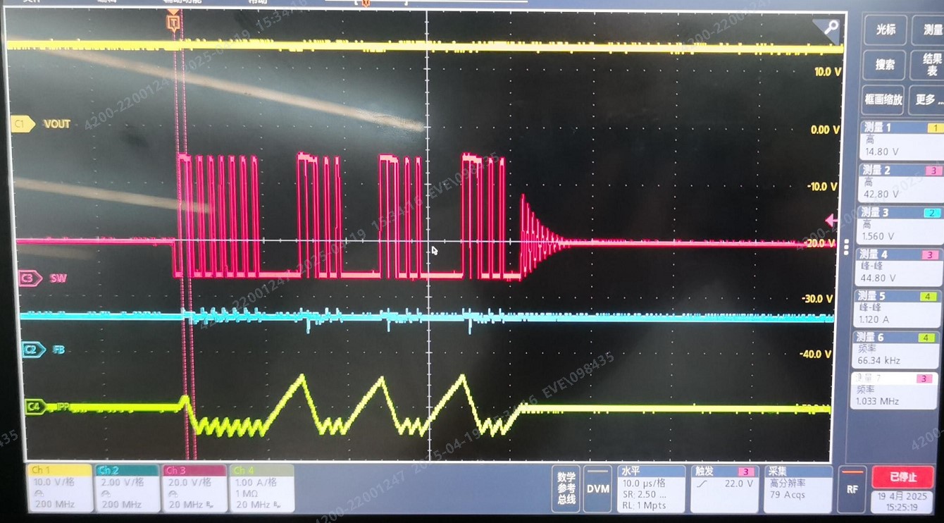
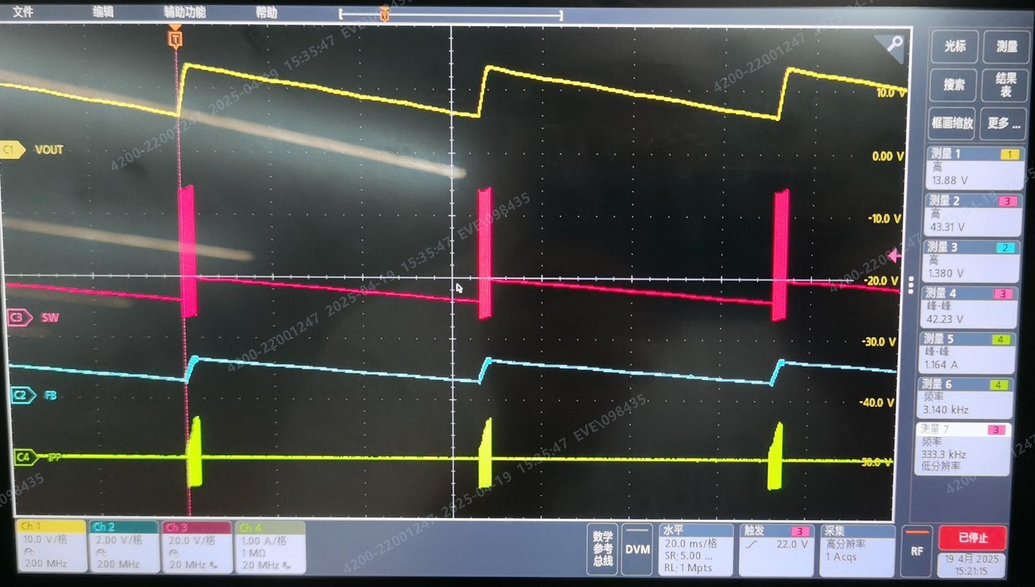
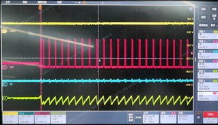
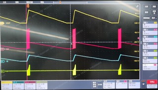
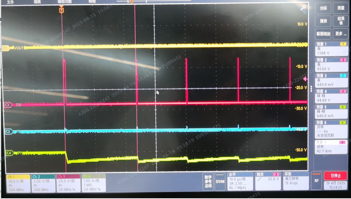
My customer use LM5168 with VIN 30V, VOUT 13.3V, when they increase current load from 0A to 10mA(electronic load CC mode), the VOUT will collapse to very low voltage about 3V-4V.

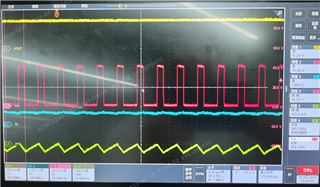
I test output voltage and current ripple, seem to be abnormally larger. So I add 100pF Cff, then it can work well. Not sure if there is something wrong with the circuit, such as loop stability?

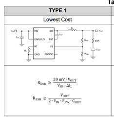
I found datasheet show we can use lowest cost circuit without any Cff or RC

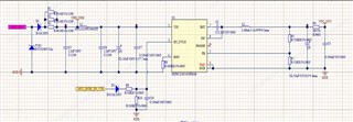
Pls help comment that. Below is schematic, note: customer actually use LM5168FDDAR, not LM5163

BR

Amber

  • Hi Amber

    Could please fill Quickstart - SNVR520 Calculation tool | TI.com to help with the review.

    Thank you

    Regards

    Onkar Bhakare

  • Hi Onkar,

    when they increase current load from 0A to 10mA(electronic load CC mode), the VOUT will collapse to very low voltage about 3V-4V.

    I fill the excel as below, I found ripple current calculation is 324mApk-pk, is that too large to cause my above issue? seems that is still below current limit in datasheet if current load I set is 10mA.

    and I don't want to ripple generation circuit so I remove Cb Ca Ra, not sure if it is suitable? voltage ripple is 11mV in calculation, but actually I test ripple is 60mVpk-pk with oscilloscope

  • Hi Amber

    Could you share the filled calculator?

    Thank you

    Regards

    Onkar Bhakare

  • Hi Onkar,

    You can open as below:

    LM5168_calc_for EVE.xlsm

    BR

    Amber

  • Hi Amber

    and I don't want to ripple generation circuit so I remove Cb Ca Ra, not sure if it is suitable? voltage ripple is 11mV in calculation, but actually I test ripple is 60mVpk-pk with oscilloscope

    - As you are using electrolytic capacitor at the output, it's ESR might be able to provide sufficient ripple for the proper operation

    Can you provide datasheet of output electrolytic cap to confirm this?

    I see you are using FPWM version, there is possibility that negative side current limit will hit

    Could you please probe inductor current waveform along with SW and Vout?

    Thank you

    Regards

    Onkar Bhakare

  • Hi Onkar,

    For inductor current, I'm working on with customer to check if has large negative current.

    For output capacitor ESR, there are two capacitors in parallel

    one is Aluminum  electrolytic capacitor(33uF), datasheet below:

    I calculate ESR followed by ESR=tanδ/(2*pi* f)*C=0.12/2*pi*120*33u=4.8ohm

    ECV1VVZ2330M0605V1.pdf

    Another is X7R ceramic capacitor with 100nF/50V/0603 , datasheet below:

    风华高科_7.pdf

    ESR=tanδ/(2*pi* f)*C=0.015/2*pi*1000*100n=23ohm? I think it is too large, maybe something wrong with my calculation

    then should I calculate the two ESR in parallel ? 

    BR

    Amber

  • Hello Amber

    I calculate ESR followed by ESR=tanδ/(2*pi* f)*C=0.12/2*pi*120*33u=4.8ohm

    The dissipation factor is defined at 120 Hz. However, switching frequency is 334 kHz thus we cannot use the specified DF to calculate the correct ESR. Some manufactures do provide frequency response or ESR value at 100kHz, which is more relevant to switching power circuits. Looks like it is missing from the datasheet

    As electrolytic capacitor value is much higher, its impedance would dominate around switching frequency and thus we should take ESR of only electrolytic for analysis. ESR of 100nF won't come into the picture.

    Could you please share waveforms of following nodes at 0, 5mA and 10mA loads for further debug?

    1. Vout
    2. FB
    3. SW

    Thank you

    Regards

    Onkar Bhakare 

  • Hi Onkar,

    I get back to you with further test waveform VOUT/SW/FB/current through inductor  :

    0A output current:

    Zoom out:

    Zoom in:

    5mA:

    Zoom out:

    Zoom in:

    10mA:

    I found peak to peak of inductor current is very higher(actual value is >1A) than I calculated on the table, and it mostly like hiccup mode which has duration of ~64ms according to above waveform?

    Why Ipp is so high than calculation value, and what can I do to solve the issue? increase inductance(68uH now with 1.1A saturation current, I=do you think Isat of inductor is also low )?

    I found if I add Cff of 100pF, current and voltage waveform can be normal, below is 150mA waveform(peak to peak current is 520mA, a little reduced but still higher than calculation  )

    BR

    Amber

  • Hi Amber

    This looks like instability issue. Vfb is not seeing enough ripple to function properly. Thus, adding Cff is helping. Additionally, this leading to current limit violation.

    You can do either of the following changes to function it properly

    1. Add ESR of 700 mOhm in series with output capacitor, but it will increase the output ripple 
    2. Select output capacitor with ESR > 70 mOhm and place value of Cff > 68pF.

    Hope this helps

    Thank you

    Regards

    Onkar Bhakare

  • Hi Amber

    Any updates on this?

    Thank you

    Regards

    Onkar Bhakare

  • Hi Onkar,

    Thanks your recommend, customer already change the SCH about Cff 

    Seems they don't have further issue now.

    BR

    Amber

  • Okay Amber

    Thanks for the update

    Regards

    Onkar Bhakare