


Other Parts Discussed in Thread: TPS2662, TPS2661
Tool/software:
Could you verify whether TPS26600 eFuse support the 5mA load device ?
Per datasheet, minimum current limit can be set to 0.1A.
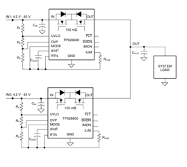
Oring-Diode solution, there are Primary VIN (12V nominal) and Secondary VIN (11.5V nominal) input power rail to the eFuse to have the primary VIN is default power supply to the rest of interfaces.
In case of the primary 12VIN power rail below the secondary input power source, then the secondary VIN will be supply power through the Oring-Diode (2nd Fuse).
Current limit set to 0.1A and maximum load current set to 5mA.
Set different slew rate at each eFuse (Primary set to 70msec and Secondary eFuse set to 1sec slew rate, dVdT)
Based on simulation, there are reverse current flows back through the secondary eFuse when the output voltage ramps up at the secondary eFuse. Even though different output voltage ramp up at eFuse, the secondary eFuse does not block reverse current.
When max load is adjust above 0.1A (also adjust I_LIM to above 0.1A), it seems the secondary eFuse blocks the reverse current properly.
Could you verify whether TPS26600 eFuse support 5mA load application even though its minimum current limit can be set to 0.1A.
If this eFuse support the 5mA load device, do you have suggestion how to prevent the reverse current flowing through the secondary eFuse ?
// Simulation

