


Tool/software:
Hello Team,
I'm designing an LLC converter with following specifications: -
Nominal Input voltage :- 665V
Minimum Input voltage :- 650V
Maximum Input voltage :- 680V
Vout :- 55V
Pout :- 150W
Consideration,
Resonant Frequency :- 100kHz
Lm/Lr = 5
Q = 0.56
Below are the calculation results,
Turns ratio of Lm = 6
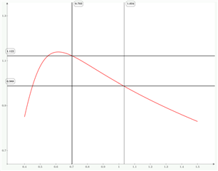
Mg_max = 1.122
Mg_nom = 1.011
Mg_min = 0.988
Cr = 4.8nF
Lm = 2.6mH
Lr = 524uH
With the above values I plotted a graph of 'LLC gain' vs 'Nominal Frequency', the gain curve cuts the 'Mg_max' and 'Mg_min' as shown below,
But, if I consider the tolerances of LLC tank components i.e. 10% for the magnetics and 20% for the capacitor, all the parameters gets changed Lm, Lr, Cr, k and Q.
Q varies from 0.485 to 0.656.
- Below is the graph with Q as 0.485 and considering tank values changes as well
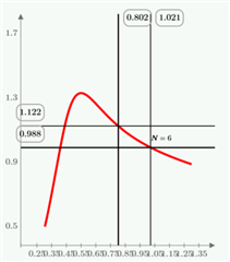
This graph shows that we are able to achieve the gains with new tank values considering variation i.e Mg_max and Mg_min lines intersect with the gain curve.
- Below is the graph with Q as 0.656 and considering tank values changes as well
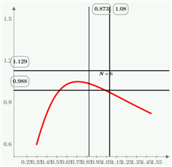
This graph shows that with Q as 0.656 and the variation in tank components the Tank gain is not sufficient enough to intersect with Mg_min and Mg_max.
How can I take care of the variations which are caused by the tolerances of the tank components and also meet the gain requirement?
Can you please suggest any solutions for this?
Thanking you in advance,
Regards,
Dilip R