This thread has been locked.

If you have a related question, please click the "Ask a related question" button in the top right corner. The newly created question will be automatically linked to this question.

TPS23881B: TPS23881 Power

Part Number: TPS23881B

Tool/software:

Hi Dear experts,

I want to use TPS23881B in autonomus mode. I have a question to be sure.

Do I need any micro controller to upload a code to use it in autonomus mode? Or should I just connect AUTO pin (52) to ground?

Best regards,

Kerim

  • Hi Kerim,

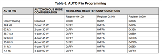
    Autonomous mode does not need a microcontroller to configure, only need to tie AUTO (pin 52) to ground using the correct resistance value based on your expected default operation.

    Regards,

    Brandon

  • Hi Brandon

    Thank you for your response. I have another question. I want to use 5 port; 2 port will be 4 pair (90W) and 3 port will be 2 pair (30W)

    I know with 7.7K all port should be 90W. if ı add 7.7k to pin 52 what will happened to the 2 pair ports? 

    Do they supply 30W or they don't work?

    Best regards

    Kerim

  • Hi Kerim,

    Unfortunately, you can only have one base default operation. Therefore, if you intent to have 4-pair 90W ports you will need to keep all ports at this power based on the pin configuration. When the internal ROM of the device boots, pin 52 uses a shot current to measure the voltage to determine the resistance value, based on this resistance value the device will pre-configure according to the above chart, therefore if you place a 7.7kohm resistor you would inherently be changing the equivalent resistance that the device will read.

    If you need to have different configurations per port, I would recommend using the device in AUTO/SEMI-AUTO mode which requires some type of I2C control.

    Regards,

    Brandon

  • Hi Brandon,

    Thank you for your response. I will use Autonomus mode wirh 7.7K. So I want to be sure about the connection of some pins.

    how should be SDAO, SDAI, SCL, INT and OSS pins.

    Should I keep them floating?

    And Can I use the circuit in the image for RESET pin?

    Best regards,

    Kerim

  • Hi Kerim,

    Here are my comments:

    SDAO: open-drain can be left floating

    SDAI: GND

    SCL: GND

    INT: open-drain can be left floating

    OSS: active high and internally pulled to GND. Can be left floating or GND.

    RESET that circuit is fine, the stability cap may not be necessary does not hurt. 

    Regards,

    Brandon

  • Hi Brandon, 

    Could you please review the connection?

    SDAI and SCL: Do you mean directly to GND without any resistors? 

    best regards

    kerim

  • Hi Kerim,

    You may use 0ohm resisters to pull to ground, these are open-drain outputs so not an issue to directly tie to ground. I would recommend 0ohm resistor for proto builds incase you need to probe or test with I2C lines.

    Would recommend 10nF ceramic cap in parallel with 7.7kohm R on auto pin for deglitch. 

    Regards,

    Brandon

  • Hi Brandon,

    I hope this message finds you well. 

    Could you please revieve the schematic?

    RJ1, RJ2, RJ3, RJ4 are net tie I just added them for layout.

    TVS dioedes mnp is SMF58A-E3-08, same as in EVB.

    TPS23881B schematic.pdf

    Best regards 

    Kerim

  • Hi Kerim,

    I have transitioned roles within TI but will re-assign this thread to the PoE team and one of their apps experts will take a look. Thank you!

    Regards,

    Brandon

  • Hi Kerim,

    The schematic looks good to me.

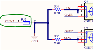
    A minor comment that the KSEN wire should be connected very close to Rcs (R34 R35 in below) to ensure good Kelvin connection for accurate current sensing. 

    Best regards,

    Diang