This thread has been locked.

If you have a related question, please click the "Ask a related question" button in the top right corner. The newly created question will be automatically linked to this question.

BQ25892: Problems when powering the battery charger with a solar panel.

Part Number: BQ25892
Other Parts Discussed in Thread: DRV8220, BQ25190, BQ25186

Tool/software:

Greetings.

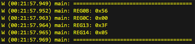
I'm currently developing a board which uses the BQ25892 battery charger to charge a Li-ion battery of 3.7 V/2200 mAh. It's powered by a solar panel of 5V/200 mA. I've made several test, and the battery charger seems to work fine, when it's powered by an external lab power supply. But, when I connect the solar panel, and the battery is attached, although through my multitester I can see around 120 mA of current flowing to the board, in the console of the firmware, in which I log the current and voltage of the battery charger, I see 0 A of current, as you can see in the following images:

My first thought of why this could be happening is that, because the board itself consumes more current than the solar panel can provide, maybe around 150-200 mA, this causes the BQ25892 to not turn ON correctly, and let the battery provide current to the circuit via the BATFET, and that's why I see "0 A", because when the BQ25892 is not ON, it doesn't show the current, just the voltage.

Just in case, I configured all the charging currents, ICHG, IPRECHG and ITERM, to 64 mA, which is below the 120 mA that the solar panel is providing.

Any ideas of what could be happening? Thank you in advance. Let me know if any more information is needed.

  • Hello,

    We are looking into this and will respond by the end of the day.

    Sincerely,

    Wyatt Keller

  • Greetings Wyatt.

    Great, will wait then, thank you.

    Best regards,

    Franco.

  • Hi Franco,

    Is there a load connected to the BQ Charger other than the battery in this scenario?

    Best Regards,

    Juan Ospina

  • Greetings Juan.

    I see that you also commented in my other post, which is "DRV8220: MCU resets when driving a solenoid latch valve". So this is basically the same circuit as the one in that post Grin

    But just in case, the BQ powers a 3V3 switching power supply, which then powers the rest of the circuit, composed of an ESP32, the DRV8220 for the valves, a RAK3172 LoRaWAN module, and some other minor components.

    However, in this case I wasn't switching the valves, I was just using the ESP32 and RAK3172. That's why I said that the load consumes around 150-200 mA. 

    Let me know if that answered your question.

    Best regards,

    Franco.

  • Hi Franco,

    It sounds like the current you are measuring is being used to power the load and may not necessarily be able to charge the battery. There is a few possible causes for why there is insufficient current to power the system load and charge the battery at the same time:

    - IINLIM / ILIM - The input current limit is limited by the lesser of the two settings between the ILIM pin and the IINLIM register value. Confirm that both of these are enabled to allow pulling more than 120mA

    - VINDPM - Since you mentioned solar inputs, it is very possible that VINDPM is limiting the amount of input current that you can pull. This happens typically with high impedance sources where a smaller current load can cause a larger voltage drop. You mentioned a source of 5V and 200mA, I would confirm panel current available at the measured VIN voltage.

    - ICO - If ICO is enabled this can limit the amount of current that you can pull from your input source to what is identified as the maximum power point.

    Can you please share register values when in this current limited state. All registers are preferred, but particularly REG 0B, 0C, 13, 14.

    Best Regards,

    Juan Ospina

  • Greetings Juan.

    I will answer point by point:

    • ILIM: I've put a resistor of 195 Ohm to that pin, which, for a KLIM of 390 A*Ohm, gives me a ILIM of 2 A, and in IINLIM, I've put the value of 0x3F, which gives me a value of 3.25 A, so in both cases, I'm way above the 120 mA
    • VINDPM: I think I didn't understand what you asked. You are saying that I should measure the input current of the solar panel?
    • ICO: It's disabled, because I put a 0 in the bit "ICO_EN" of the REG02.
    • REGS: Of course. Here are the values for each REG that I've configured, taken from my firmware:

    BQ25892_REG00_t reg_00 = {
        .EN_HIZ = HIZ_MODE_DISABLE,
        .EN_ILIM = ILIM_PIN_ENABLE,
        .IINLIM = 0x3F, // 3.25 A de ILIM
    };
    
    BQ25892_REG02_t reg_02 = {
        .AUTO_DPDM_EN = AUTO_DPDM_EN_DEFAULT,
        .FORCE_DPDM = FORCE_DPDM_DEFAULT,
        .MAXC_EN = MAX_CHARGE_ADAPTER_DEFAULT,
        .HVDCP_EN = HIGH_VOLTAGE_DCP_EN_DEFAULT,
        .ICO_EN = ICO_DISABLE,
        .BOOST_FREQ = BOOST_MODE_FREQ_SEL_DEFAULT,
        .CONV_RATE = CONTINUOUS_CONV,
        .CONV_START = START_CONV,
    };
    
    BQ25892_REG03_t reg_03 = {
        .SYS_MIN = 0x00,    // 3V de SYS_MIN
        .CHG_CONFIG = CHARGE_ENABLE,
        .OTG_CONFIG = OTG_DISABLE,
        .WD_RST = NORMAL,
        .BAT_LOADEN = BATTERY_LOAD_ENABLE,
    };
    
    BQ25892_REG04_t reg_04 = {
        .ICHG = 0x01,   // 64 mA de ICHG
        .EN_PUMPX = CURRENT_PULSE_CONTROL_DISABLE,
    };
    
    BQ25892_REG05_t reg_05 = {
        .ITERM = 0x01,  // 64 mA de ITERM
        .IPRECHG = 0x01,    // 64 mA de IPRECHG 
    };
    
    BQ25892_REG06_t reg_06 = {
        .VRECHG = _200mV,
        .BATLOWV = _3V,
        .VREG = 0x17,   // 4.208 V de voltaje de carga
    };
    
    BQ25892_REG07_t reg_07 = {
        .JEITA_ISET = _20_perc_of_ICHG,
        .CHG_TIMER = _12_hs,
        .EN_TIMER = CHG_SAFETY_TIMER_ENABLE,
        .WATCHDOG = DISABLE_WDT,
        .STAT_DIS = STAT_PIN_ENABLE,
        .EN_TERM = CHARGING_TERMINATION_ENABLE,
    };
    
    BQ25892_REG09_t reg_09 = {
        .PUMPX_DN = CURRENT_PULSE_CONTROL_VOLTAGE_DOWN_DISABLE,
        .PUMPX_UP = CURRENT_PULSE_CONTROL_VOLTAGE_UP_DISABLE,
        .BATFET_RST_EN = BATFET_SYS_RESET_DISABLE,
        .BATFET_DLY = BATFET_TURN_OFF_DELAY_DISABLE,
        .JEITA_VSET = VREG,
        .BATFET_DIS = BATFET_ON,
        .TMR2X_EN = SAFETY_TIMER_NOT_SLOWED_BY_2X,
        .FORCE_ICO = DONT_FORCE_ICO,
    };

    You mentioned registers 0B, 0C, 13 and 14. But they are almost all read only registers, so there's no configuration of current limit in them I think. Is this right?

    Best regards,

    Franco.

  • Hi Franco,

    You mentioned registers 0B, 0C, 13 and 14. But they are almost all read only registers, so there's no configuration of current limit in them I think. Is this right?

    That's right, I'm hoping to get readback values to understand the state of the device while in this state.

    ILIM: I've put a resistor of 195 Ohm to that pin, which, for a KLIM of 390 A*Ohm, gives me a ILIM of 2 A, and in IINLIM, I've put the value of 0x3F, which gives me a value of 3.25 A, so in both cases, I'm way above the 120 mA

    As long as IINLIM isn't reset by a watchdog then these should be fine for your application.

    VINDPM: I think I didn't understand what you asked. You are saying that I should measure the input current of the solar panel?

    VINDPM limits the input voltage current due to a drop in input voltage. This is common with high-impedance input sources, like solar panels. Can you measure the VIN voltage close to the IC? 

    Best Regards,

    Juan Ospina

  • Greetings Juan.

    Sorry for the delay. Regarding the registers that you mentioned, I see. Then allow me some time, given that I've to add the request of those registers to the firmware, because I don't have done it right now.

    Regarding IINLIM, I would say that no, there's isn't a watchdog that is reseting that value.

    Regarding VINDPM, I understand. If I remember correctly, I measured the VIN voltage in the test I've made, and I think it was around 6-7 V. But just in case, I will measure it again after I've added the request of the registers that you mentioned to the firmware, so again, allow me some time to do this.

    Best regards,

    Franco.

  • Hi Franco,

    Thanks for the update. The registers should help us know what direction to look in in terms of cause.

    Best Regards,

    Juan

  • Greetings Juan.

    Sorry for the delay. I was able to modify the firmware so I can visualize the values of the registers you suggested. The problem is that, right now, we're having some rainy days, so the solar panel is able to produce 10 mA of current as much, sadly. So I'll have to wait for the sun to appear, so I can get at least 80 mA of current.

    But, in the meantime, here are the values of the registers 0B, 0C, 13 and 14, with the board powered by my lab power supply:

    I've verified those values with the datasheet, and 0C, 13 and 14 seem right, but there's something strange with REG0B. Because a value of 0x56 means that:

    -VBUS_STAT: 0b010 -> Adapter (3.25 A), which is correct.

    -CHRG_STAT: 0b10 -> Fast charging, which seems incorrect, given that the battery is not even connected in this test.

    -PG_STAT: 0b1 -> Power good, which is correct.

    -RESERVED: 0b1 -> Which seems incorrect, because, according to the datasheet, "always reads 0".

    -VSYS_STAT: 0b0 -> Not in VSYSMIN regulation, which seems correct.

    Is this normal?

    Best regards,

    Franco.

  • Hi Franco,

    These register readings all seem fine, there's nothing here to indicate that a input or charge current should be limited. I was looking for something like VINDPM or IINDPM.

    With the bench power supply, are you seeing the same current limitations as you were seeing with the solar panel?

    Do you have a way of verifying BAT Current other than using the onboard ADC?

    Best Regards,

    Juan Ospina

  • Greetings Juan.

    Oh, okey. And in your opinion, that value for the REG0B is correct?

    Regarding your first question, no, when I use my bech power supply, the battery charges correctly. I've even try charge current values up to 1 A, and it works fine. This is not the case when using the solar pannel, of course.

    Regarding your second question, you mean that if I can measure the current that's reaching the battery when I use the solar pannel with something? If that's the case, maybe I can use my digital multimeter, which is the one I used to check the input current when using the solar pannel. But again, because right now there're a lot of clouds in the sky where I live, I have to wait for the sun to appear, so I can get a higher current value.

    Best regards,

    Franco.

  • Hi Franco,

    Oh, okey. And in your opinion, that value for the REG0B is correct?

    Yes that looks fine.

    Regarding your first question, no, when I use my bech power supply, the battery charges correctly. I've even try charge current values up to 1 A, and it works fine. This is not the case when using the solar pannel, of course.

    Ah, understood. Once the solar panel is available again, it would be good to recapture the indicated register values. In this scenario you do read the correct ADC current? If so then the following point may be unnecessary:

    Regarding your second question, you mean that if I can measure the current that's reaching the battery when I use the solar pannel with something? If that's the case, maybe I can use my digital multimeter, which is the one I used to check the input current when using the solar pannel. But again, because right now there're a lot of clouds in the sky where I live, I have to wait for the sun to appear, so I can get a higher current value.

    During your original question, the indication that there was no current going into the battery appeared to  be based on the ADC reading from the device register. I just meant to recommend a sanity check that the ADC reading matched a physical measurement that you might use to verify behavior.

    Best Regards,

    Juan Ospina

  • Greetings Juan.

    Ah, understood. Once the solar panel is available again, it would be good to recapture the indicated register values. In this scenario you do read the correct ADC current? If so then the following point may be unnecessary:

    Yes. When using my bench power supply, I've verified that the current read by the ADC matches the real current going to the battery. But just to be sure, I'll check that when using the solar panel.

    I hope to be able to test the solar panel again tomorrow.

    However, lets say that I do that test and the battery still doesn't charge. I was thinking that maybe this model of battery charger is not fit to work with such low currents. If I'm not mistaken, there should be some other models of battery chargers that are suitable for working with solar panel, which supply pretty low currents. Is this correct? Or this model technically should work with these current levels?

    Best regards,

    Franco.

  • Hi Franco,

    The BQ2589x can be programmed to charge as low as 64mA in battery current with pre-charge and termination at around the same range. Our other single-cell switching chargers operate in a similar range of current options. Our linear chargers such as the BQ25186 and BQ25190 have a bit more precision and are designed for a lower range of current operations.

    This model should still technically work with the current levels you are operating at if you are ok with that level of precision. If you want more precision at the cost of some input efficiency you can take a look at the linear chargers I've mentioned.

    Best Regards,

    Juan Ospina

  • Greetings Juan.

    Yes, after thinking it a bit, I think that, for this application and the level of currents that I've tested, it would be a better idea to use a different battery charger model. I looked at the datasheet of BQ25186, and it says that the configurable range of the charging current is 5-1000 mA:

    So I think it would be a good option, because when working with solar power and batteries, all the current that you can gather is worth it. I will proceed with the design of a new prototype then, and not put more time in tests with BQ25892. Thank you very much for your help.

    Best regards,

    Franco.