This thread has been locked.

If you have a related question, please click the "Ask a related question" button in the top right corner. The newly created question will be automatically linked to this question.

HD3SS3220: AC-coupling capacitor placement

Part Number: HD3SS3220

Tool/software:

Hi there,

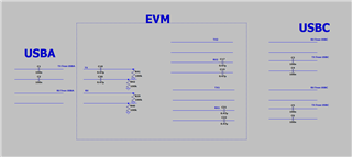
HD3SS3220 DFP Dongle Evaluation Module (Rev. A)

about the HD3SS3220 Type-C Down Facing Port EVM, I don't understand the connection of AC coupling cap(C18, C20, C17, C19, C20, C21) and pull down resistors(R39, R40, R41, R42).

1. I want to know the correlation between 470nF AC coupling and 'HD3SS3220 switch from Vcm above 2 V'. why use 0.47uF or 0.56uF can protect HD3SS3220, but 1uF can't? 

2. for C18, C20, it is place on the TX side of USBA, why it can protect the RX of USBC? if follow the spec, on the USBA side, there should be AC coupling on the board that connect to this dongle, why extra AC cap is needed.

3. why the pull down resistor, is this to bias the RX signal down to GND? but why there is still DC bias after AC coupling cap?

4. I am searching the USB spec, and I see a statement, quote 'The receiver designs must survive legacy implementations with VTX-DC+AC_CONN common mode transient up to 2.2V', is this statement relate to AC coupling and pull down on the EVM?

thanks a lot!

  • Hi,

    1) The AC caps are to set the common mode of any incoming signal to 0, by blocking ay DC common mode. The AC capacitors are placed on both sides of the mux to guarantee operability with devices and host with common mode outside of the HD3SS3220 spec.

    When AC capacitors are on both sides of the signal path, then the common mode of the mux is undefined/ floating. The pull down resistors are to keep the floating net between the two AC coupling capacitors at a known value of 0V. 

    2) 1uF would slow down the edges of the USB signal too much. The values of 470nF are used here so the USB bus capacitance spec if not exceeded.

    3) No sure which resistor you are referring to.

    4) Yes this is why we must double AC couple the EVM.

  • Hi Vishesh,

    thanks for your reply.

    for your answer #1, the AC coupling cap is not place on both sides of the MUX. it is only place on TX side follow the USB spec. also as you mention, 'AC caps are to set the common mode signals to 0', then why we need extra AC caps if the incoming signal is already AC coupled on the USBC/USBA board?


    for your answer #2, 470nF is not within the USB spec. but 470nF in serial with 100nF gives total 82nF, and it is within spec. 1uF serial with 100nF doesn't change much on the total capacitance(90nF), and it is within USB spec. 

    for #3, R39, R40, R41, R42.

    for your answer #4, the total AC coupling is divided by half. why half/double the AC coupling affect the common mode transient.

    thanks a lot!

  • Hi,

    1) The capacitance circuit is not necessary. It is in place to make sure the EVM will work with any USB device or host, even if those devices and hosts are not complaint. We do not know what parts will be plugged into the EVM, so to avoid damaging the part with out of spec common mode voltages we devices we added the additional .47uF capacitors.

    2) Yes, this logic is correct. The reason we did not use a larger cap like 1uF for more tolerance in bus capacitance is due to the dace that such a large cap on the signal path will impact the rising edges and falling edges of the data degrading signal integrity. 

    3) this is to put all signals at a known level, as there is a possibility that a host system with RX caps is used. If such a host system is used, then then the mux common mode voltage will be floating. These resistors put it in a known state. They also provide the additional functionality of discharging the caps faster in the vent of a hot plug. 

    4) The AC coupling sets the common mode to 0V by blocking any DC common mode. This is how the caps address this. The total bus capacitance will remain within spec, but in this EVM implementation the common mode of the HD3SS3220 is always 0V.

  • Hi,

    I'm closing this thread due to inactivity.