Tool/software:
Hi team,
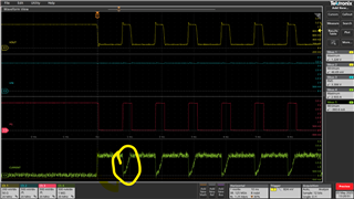
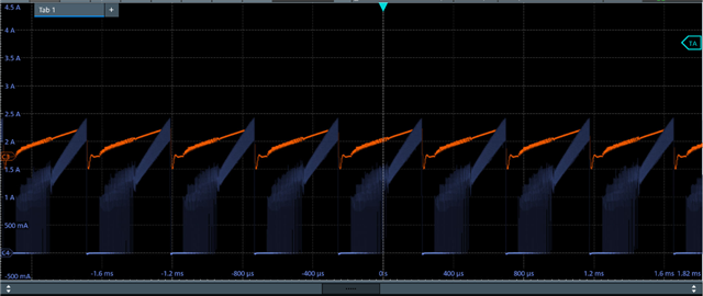
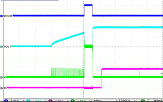
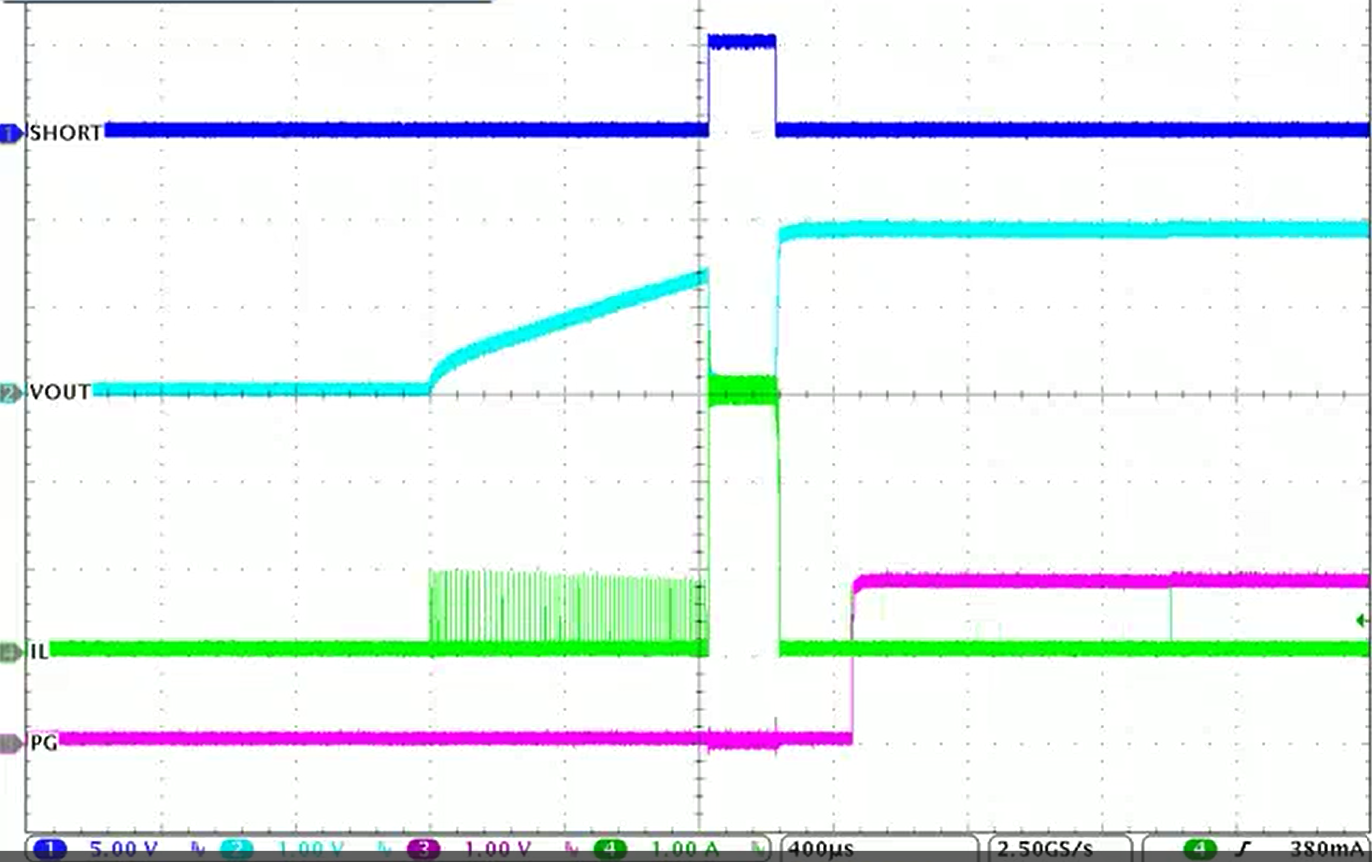
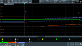
We would like to inquire about short circuit test using an e-load set to 0.05 ohm in CR mode.
The waveform is as shown below.

Could you please help check if the behavior is correct and explain it?
Thank you.
Tool/software:
Hi team,
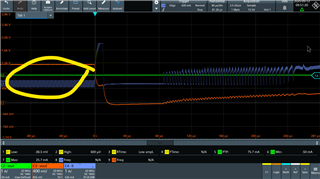
We would like to inquire about short circuit test using an e-load set to 0.05 ohm in CR mode.
The waveform is as shown below.
Could you please help check if the behavior is correct and explain it?
Thank you.