This thread has been locked.

If you have a related question, please click the "Ask a related question" button in the top right corner. The newly created question will be automatically linked to this question.

UCC25800-Q1: No sinusodial current in light load mode

Part Number: UCC25800-Q1


Tool/software:

Hi team,

I have read several forum entries and application notes, but have not found a solution.

We have a circuit with FOUR transormers, secondary side LLC and voltage doubler (see schematic).
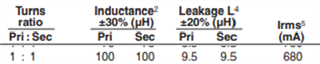
Transformer: 

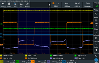
Under load (e. g. 100 R @ 20 V => 400 mW, also works with 200 R and so on...) we have the following wave forms:

Ch 1 : positive voltage at output 1 (100 R)

Ch 2 : positive voltage at output 2 (no load)

Ch 3 : primary side switching voltage

Ch 4: transformer secondary side (pin 3) current at output 1

As you see, the current looks good (I know, that fine tuning is still necessary, because the sinewave is cut off).

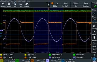
But in light load condition, we have the following wave form:

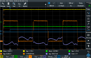
Ch 1 : positive voltage at output 1 (R = x kR)

Ch 2 : negative voltage at output 1 (R = x kR)

Ch 3 : primary side switching voltage

Ch 4: transformer secondary side (pin 3) current at output 1

I tried different switching frequencies (200 ... 1000 kHz), capacitors (2.2 ... 33 nF) ... In no case could a sinusoidal current be recognised.

Question 1: Do you have any idea what the problem could be? Do we need some kind of base load?

Question 2: As you can see on the first oscillogram, with a load of 100 R, the total output voltage (positive and negative together) drops by around 2 V if one output is loaded and the other three outputs are unloaded. Presumably no countermeasures can be taken here, correct?

Thanks in advance.

Best regards,

MS

  • Are the waveforms that show full load to no load taken when loading/unloading only a single transformer output? If yes what about the other three transformers - what is the load on xfmr1, xfmr2, xfmr3 and xfmr4?

    Steve

  • Hello Steve,
    thanks for answering.
    In the unloaded state, NO transformer is loaded (except for the aforementioned x kOhm through any voltage dividers etc.). In the loaded state, only ONE transformer is loaded. Unbalanced loads can also occur in later operation, so that, for example, three transformers are loaded less than another.

    Best regards,

    Marco

  • looks like your resonant freq is Fres=532kHz and your switching frequency, Fsw=540kHz. Seems tuned correctly for full load resonance and if this were a closed loop LLC controller, the frequency would increase as the load is decreasing and this would maintain sinusoidal input current down to a much lower load condition. However, with fixed duty cycle and fixed frequency, there is not much you can do except maybe adjust the fixed frequency such that you trade off some sinusoidal shape at full load to get back a bit at some min load? Even when using a variable frequency LLC controller, the input current shape is still distorted and should not be expected to be sinusoidal down to no load.

    Steve

  • Hello Steve,

    thanks for answering!

    I have already tested other frequencies (setting on RT via potentiometer and also via another capacitor in the resonance circuit). This gave me the following curve (in this case with higher C; ower harmonic components were achieved (the FFT was only considered visually)):

    But if it is the case that you only ever get the best result at a certain operating point at a fixed frequency, then I will look again to see which load case is critical and try to achieve the best possible result via the voltage at RT and the capacitor in the resonant circuit.

    Best regards,

    Marco

  • I have seen that the transformer is designed for over 600 mA. We only use a part of this current (maybe 100 mA). Would it be conceivable that we could achieve better results with a different transformer in terms of current shape? Or would the distortion probably also be greater in this case?
    Thanks in advance,
    MS

  • Reducing from 600mA down to 100mA is mostly going to result in sizing the wore to lower current density. Not entirely sure...build it and let us know? We do know that a certain amount of resonant inductance is required (leakage inductance) and this is one of the main target parameters of the transformer design. 

    Steve

  • Thanks for answering. 

    Unfortunately, I can't continue at this point without considerable additional work, as I haven't found any transformers with the same/similar housing and because I don't have the time.

    So I tested new designs with the switching frequency and the capacitors, which should be OK according to the literature. I also downloaded the Power Designer and used it to test a similar design. However, I can't get a sinusoidal current in the partial load range. I now have a combination that still has harmonics according to the FFT, but not as high as at the beginning.

    Thanks again!

    MS