This thread has been locked.

If you have a related question, please click the "Ask a related question" button in the top right corner. The newly created question will be automatically linked to this question.

LM5148-Q1: Sleep current issue

Part Number: LM5148-Q1
Other Parts Discussed in Thread: LM5148

Tool/software:

Hi team,

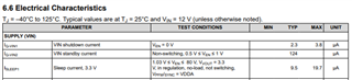
My customer used LM5148-Q1, but they tested sleep current  Isleep1/2 based on Electrical Characteristics table, '1.03 V ≤ VEN ≤ 80 V, VVOUT = 5.0 V, in regulation, no-load, not switching, VPFM/SYNC = VDDA'. But the current is ~16uA not 9.9uA. Could you please check it is correct for 16uA? Thank you.

Best regards,

Yu

  • Hi Yu,

    9.9uA is a typical value. The datasheet outlines the range as following:

    So this value is still within spec. 

    Thanks,

    Best Regards,

    Taru

  • Hi Taru,

    Thanks for your qucik reply. But, 9.9uA is typical value, usually this value should test with typical VIN and 25C. But now under 25C, 12V VIN, it is 16uA, I think it will be out of spec. like high temp and corner device. 

    Best regards,

    Yu

  • Hi Yu,

    Please share how the customer is measuring the leakage current. There have been cases of inaccurate readings when measuring such low currents. 

    Please also share the schematic of the design. 

    Thanks,

    Best Regards,

    Taru

  • Hi Taru,

    Please check schematic, removed R6, connect PFM/SYNC to VDDA, tie together FB and FB_VDD (5V fixed VOUT). And then 12V on VIN, EN=5V, OUT=6V. Measure input current. 

    Best rgards,

    Yu

  • Hi Yu,

    Can you share a higher resolution schematic? It is difficult to read this one. 

    Furthermore, for measuring current - what kind of ammeter are you using? 

    Thanks,

    Best Regards,

    Taru

  • BuckController.~(26).pdf

    Hi Taru,

    Please check attached for PDF version. It should be more clear. I used Keysight 6 1/2 multi meter for current measurment. 

    Best regards,

    Yu

  • Hi Yu,

    I am on leave today - I'll get back to you as soon as I am back. 

    Thanks,

    Best Regards,

    Taru

  • Hi Yu,

    There are a couple of things to consider:

    1. My first recommendation would be to depopulate the input EMI Filter. The C27 cap and the filter inductor will be consuming some energy because of their ESR and DCR respectively. I believe this should bring the value close to what you see in the datasheet. 

    2. The other point of difference would be the FETs. The leakage current of FETs also adds to the net input current. Please consider them as a factor as well. 

    Therefore, what you are measuring at the input side is Sleep Current of LM5148 + Leakage in Input Stage + Leakage in FETs. 

    Hope this helps. 

    Thanks,
    Best Regards,

    Taru

  • Hi Taru,

    I did not populate any EMI filter commpents. So no current into EMI filter. So you mean input side current included Sleep Current + Leakage in FETs, how do you get 9.9uA in datasheet? How do you test? Thank you.

    Best regards,

    Yu

  • Hi Yu,

    Apologies for the delay - i was out of office for the past week or so.

    how do you get 9.9uA in datasheet? How do you test?

    This is tested on our ATE bench during validation and hence doesn't include any leakage currents that are not associated with the IC. 

    i was reviewing your schematic and I see PFM/SYNC as floating - please ensure you pull it up to VDDA.

    You can also probe the switch node to ensure that there are no switching cycles seen (the device will go into sleep mode after 16 missed switching cycles).

    I also see both - Inductor DCR sensing and shunt current sensing implemented. You need to use one out of the two.  

    Thanks,

    Best Regards,

    Taru