Tool/software:
Hi again,
I want to consult with you guys again regarding the failure in my device in light of some new details and since more and more devices are failing in the field.
Please also look at the previous thread : "Sudden Failure of one of the DC-DC converter's outputs"
As a reminder: I am using this chip to obtain 3 outputs ( 2x 3.3V and 1 x 5V). The device is turned ON initially when the customer receives is and is never turned OFF from that point ON. The device is used on a daily basis (about 20 mins of usage every day) and after usage it goes into sleep mode, so most of the time the device is in sleep mode. Everything works fine for a few weeks and then suddenly the 5V output fails during sleep mode, NOT during usage. The failure is ALWAYS on the 5V output (which is configured on BUCK2). I am currently getting this failure in around 10% of my systems.
Here are some more details:
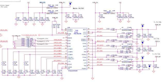
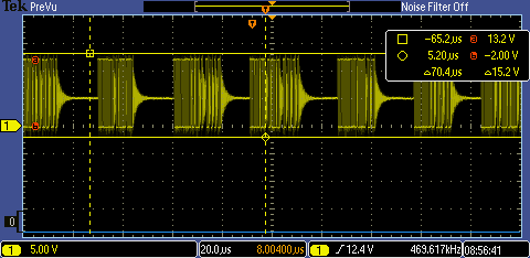
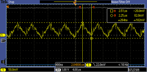
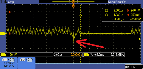
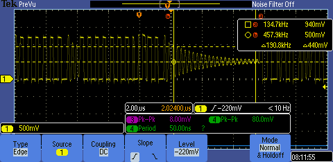
1. The 5V cycle is this : The device is turned initially turned ON when the customer receives the device. From that point on the customer never shuts down the device, so the IC is always ON, so there are no transients only the load is changing. Each daily session the most significant load comes from the speakers that are connected to the 5V output but they load the output momentarily (they prompt the customer to do some action), so I don't think that is an issue. After a few weeks of usage, the output fails during sleep mode. In sleep mode the loading on the output is very light (few 10s of mA). The IC uses PSM mode and using a scope I see that the 5V switching is in short bursts due to the light load (as opposed to the other outputs that are more heavily loaded where continuous switching with no pulse skipping is observed)
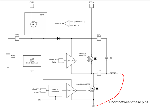
1. When the 5V output fails, the BUCK2 output is shorted to ground and the meaning of this is (correct me if i'm wrong) that the low side FET of the BUCK2 driver is damaged (see image I took from the datasheet). Is this detail useful for where I can start debugging the issue?
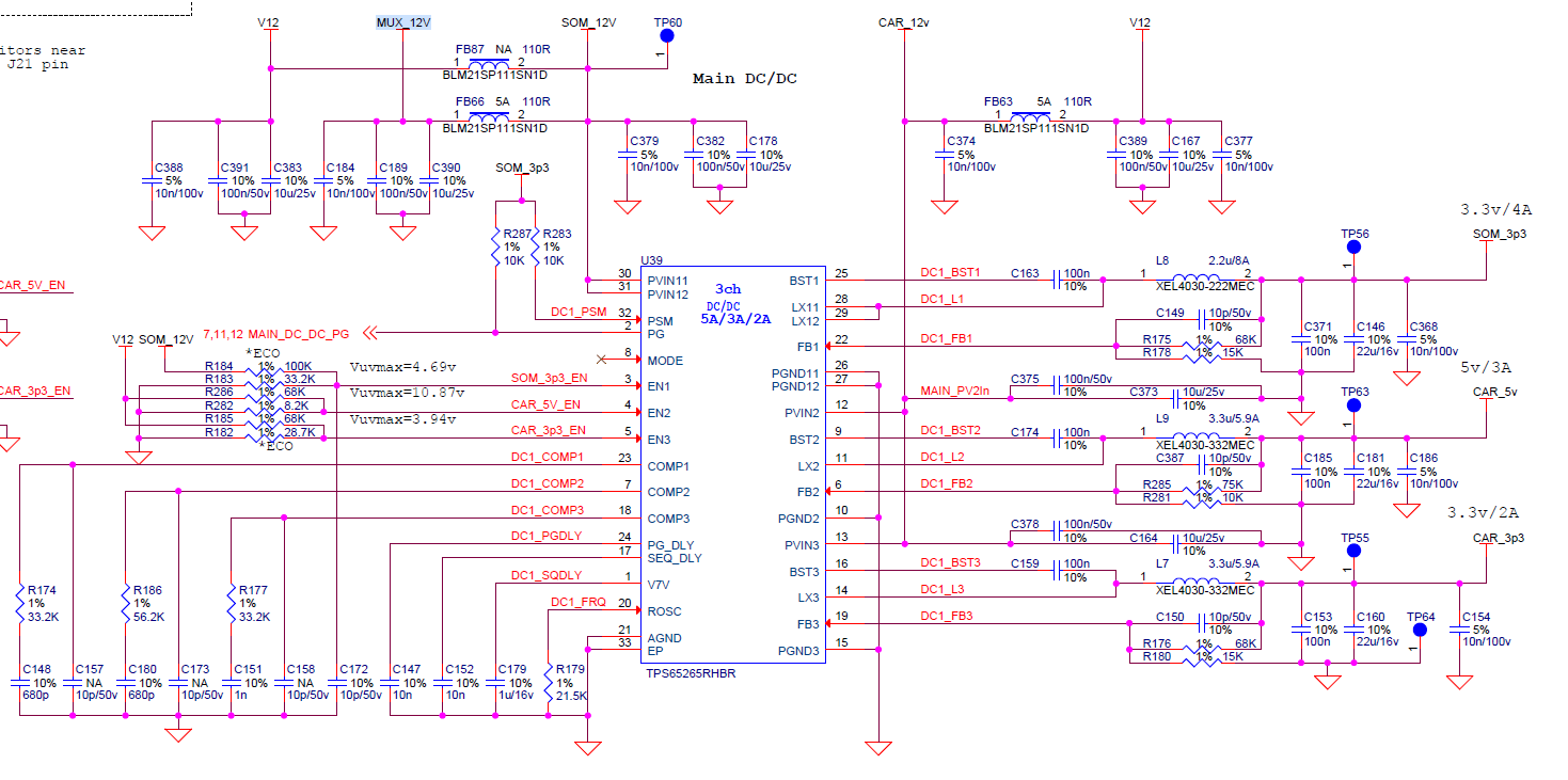
2. The PVIN1 is supplied from a different 12V (SOM_12V) voltage source than PVIN2 and PVIN3 (CAR_12V). See schematic
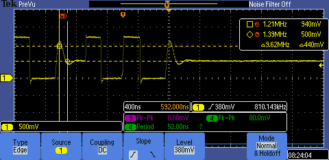
3. I looked at the 5V output using a scope and it looks stable as a rock. No spikes or any other types of transients.
4. I came across this TI application report : SLUA962 which talks about damage to the low side FET due to reverse current and was thinking that maybe because the 5V output is very lightly loaded but has a relatively high capacitance (22uF) there might be a condition that the output voltage is higher than the input voltage when the device is turned OFF if the input voltage falls off more quickly than the 5V output. The problem with this theory is that the device is only turned ON and then OFF at several steps of the manufacturing when the device is tested, calibrated, etc... On the other hand the device is never turned OFF after the customer turns it ON initially. So if this is the root cause then the failure is occurs during manufacturing and but manifests itself only later. Does this sound plausible?
A different theory is that there was a temporary power outage at the customers home that created the condition for the reverse current.
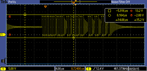
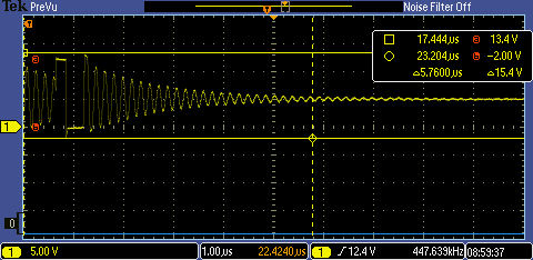
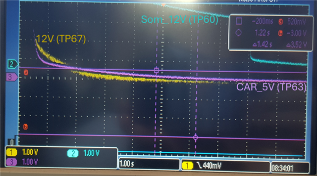
Moreover using a scope I did see that the 12V which supplies the 5V (PVIN2) output does indeed fall quicker than the 5V (see scope image, disregard blue trace, which is the 12V input to PVIN1) but the difference is very small (maybe few 10s of mVs) and the time at which the voltage on the 5V output becomes higher than the voltage on the 12V input is many miliseconds after the EN pin has been turned OFF (there is no switching going ON in the driver anymore)
Please help me debug this issue if possible.
Thanks again,
Eviathar
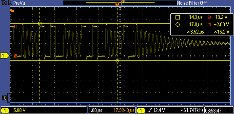
Here is the schematic again :