Tool/software:
ear TI Support Team,
Hello,
We are currently developing an automotive LED driver circuit and have adopted the TPS92624-Q1 as a key component in our design.
We truly appreciate the technical documentation provided in the datasheet, which has been very helpful.
However, the functional block diagram (Figure 7-2) and the I/O structure (Figure 7-11) are presented at a high level of abstraction, making it difficult to clearly understand the internal operation of the Logic block — particularly in the context of design reviews and FAULT Bus implementation.
To ensure system reliability and safety, we would like to inquire whether it is possible to obtain more detailed documentation or an internal block diagram that covers the Logic block, including the following aspects:
 Specifically, we are looking for information on:
Internal decoding of PWM input signals and per-channel dimming control
Diagnostic operation flow (e.g., LED open/short detection, overcurrent conditions)
Behavior of the FAULT pin (input sensing vs. output sinking logic)
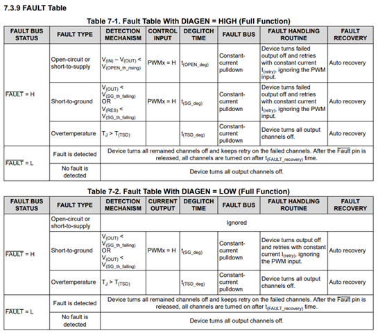
Effect of the DIAGEN pin on diagnostic operation and output shutdown behavior
This information would serve as an essential reference for designing a robust FAULT Bus configuration and implementing reliable per-channel current control logic in a multi-channel system.
If there are any application notes, internal block diagrams, or flowcharts related to the items above, we would greatly appreciate it if you could review the possibility of sharing them.
Thank you very much for your support.