This thread has been locked.

If you have a related question, please click the "Ask a related question" button in the top right corner. The newly created question will be automatically linked to this question.

BQ24195: BQ24195 can't power up after shipping mode

Part Number: BQ24195


Tool/software:

I have some products that use the BQ24195. At the end of manufacturing assembly, the devices are commanded into shipping mode. At this point the power is disconnected from the VBUS pins while the battery stays connected and is at about 3.9 V. ON re-connection of 5 V to the VBUS pins, the PMIC will not power up.

The steps are:

  1. Product is powered from 5 V supply on VBUS and battery is connect at about 3.9 V. The PMIC is put into Shipping Mode. The product remians power until the 5 V supply is disconnected.
  2. In this unpowered state, REGN ~ 0 V (normal operation) and VBUS discharges to approx. 3 to 5 mV (proper conditions for the device to have powered down)
  3. The 5 V power supply is reconnected to the product and VBUS is measured to be approx. 5.05 V. The product does not power up and REGN remains at approx 0 V.

The only way to get the PMIC to power up again is to completely disconnect ALL power sources, including the battery, so that the PMIC returns to its factory settings (I am assuming that's what happens when the PMIC loses all power).

These products are using a lithium polymer battery that have a built-in temperature sensor, and the temperature sensor is connected to the TS pin of the PMIC. I'm looking through the BQ24195 datasheet to see if an out of range voltage at the TS pin prevents the PMIC from powering up again after shipping mode, but I haven't found those details yet. Can you tell me if an out of range TS voltage prevents the PMIC from powering up?

I read another similar post about a PMIC not exiting shipping mode but there was no resolution in that thread.

Can you suggest some reasons why the PMIC won't exit shipping mode?

  • Hi,

    Typically for shipmode exit a VIN plug in should be sufficient to exit shipmode again. If you're unable to exit shipmode with a VIN assertion, that might be indicative of a device lock-up due to I2C being disabled when the BATFET is disconnected.

    Is the issue very reproducible on any units? If so can you please provide a waveform of the failure? Additionally, rather than entering shipmode when in Battery only mode, can you try first writing REG07[5] = 1 with VIN still attached, then removing VIN to see if Shipmode can be exited normally after VIN has been re-asserted?

    Best Regards,

    Juan Ospina

  • Yes, I agree. The PMIC appears to see all the necessary conditions for it to exit shipping mode, but it doesn't.

    How would the I2C get disabled when the BATFET is disconnected?

    Yes, I can capture waveforms, but exactly what waveforms do you want to see?

    I may not have been very clear, but we are already doing as you asked: the is a 5 V power source connected to the VBUS pins AND the battery is connected (at 3.9 V, or so), and then the PMIC is put into shipping mode. The device remains powered until the 5 V power source is disconnected at which point the product is no longer powered as is expected. When the 5 V power source is re-connected, the PMIC won't power up (REGN remain at 0 V and the the SYS pins are at 0 V).

  • Hi,

    For the waveform, can you provide a capture of the SDA/SCL lines during the I2C transaction to have the Q4 FET disabled, along with the SYS Voltage Rail?

    Additionally, can you provide a couple waveforms including VIN, VPMID, VSYS, VSW, and VBAT when attempting to exit shipmode?

    Best Regards,
    Juan Ospina

  • I captured all the plots you wanted to see. Some words of explanation...

    First, we are using a module from Particle that contains an STM32 microcontroller and a UBLOX cellular modem. We have built a carrier PCB into which the Particle module plugs, and it's the Particle module that runs the application code. The BQ24195 PMIC is on out carrier PCB with a dedicated I2C bus that goes to the Particle module. Particle has written an Operating System, OS, that implements a "SHipIt" command. I will have to find out exactly what I2C commands are sent to the PMIC when the ShipIt command is given, but my guess is the commands are the ones in the BQ24195 datasheet to disable the watchdog and then open the BATFET.

    This I2C capture shows a portion of the SCL and SDA transaction when the ShipIt command is sent. Something I haven't told you yet is this error state doesn't occur all the time. In other words, my product can be powered with both the battery and the 5 V source, a ShipIt command given, and the 5 V source disconnected and re-connected and the PMIC will power up properly. It seems to take several cycles to get the PMIC into this error state where it can't get out of shipping mode.

    I have described all of this to say that the portion of the I2C transaction I captured was probably not the one that initiated the error state. Below is the I2C bus transaction - the yellow trace is SCL and the blue trace is SDA:

    I finally got this PMIC into the error state (after several cycles) to capture the other plots you requested as the PMIC tried to exit the shipping mode when the 5 V source was re-connected. I only have a 2 channel oscilloscope so I captured all the signals relative to re-connecting Vin (the 5 V power source). I captured 4 plots: Vin and VPMID, Vin and VSW, Vin and VSYS, and finally Vin and VBAT. I am only showing you one of the 4 plots because they all look the same.

    I have never used the OTG boost feature that's on this PMIC, but it looks to me like maybe the PMIC is in boost mode. And because the BATFET is open, the boost is not regulating properly which is causing the large voltage swing. Note that the large voltage swing only exists when the 5 V source has been connected in an attempt to bring the PMIC out of shipping mode. Further, once in this state, the PMIC stays in this state until all power has been disconnected (both the 5 V source and the battery), after which the product will power up normally.

    The plot below is Vin and VPMID - the yellow trace is Vin and the blue trace is VPMID:

    You can see that Vin, and in this plot so to is VPMID, is swinging to 165 Vpp. This is why I think the PMIC is in boost mode.

    Again, all the other plots look identical - the blue trace, whether it is VSW, VSYS, or VBAT, is always the same peak-to-peak swing as Vin.

    What do you think?

  • Hi Anthony,

    Not sure if I'm understanding this correctly but if the VIN voltage is swinging from -84 Volts to 81 Volts then this is far outside the expected or safe range of operation for pins on this device. The device wouldn't be able to Boost to those voltages so I would expect this is indication that either something is shorted to a high power rail or there is an issue in the probing. If this waveform is really being shown on all the mentioned nodes then I would imagine the device is damaged and not properly regulating at this point. Can you confirm that these are the actual voltages measured on those pins via a DMM or other instrument?

    Best Regards,

    Juan Ospina

  • Now that you say that I'm not 100% confident in my probing. I'll have to check that again.

    Today I have connected a logic analyzer to the I2C path from the host to the PMIC. I mentioned before that my product uses a module that contains the host MCU (microcontroller) which is connected to the PMIC on my product. The module manufacturer has written an OS for the MCU, and they have written a "ship-it" function. Our firmware sends the ship-it command. I have been using the logic analyzer to see exactly what i2c transactions implement their ship-it command.

    It looks like the ship-it command reads the REG05 and then write the exact same value back to REG05. It just so happens that the watchdog is not enabled which is why they can write the same value back to REG05 - the watchdog is already disabled. Then they read REG07 and then write a value to REG07 that turns off the BATFET. So this part makes sense.

    What is the correct procedure for placing the PMIC in shipping mode? Would you say the that the best way would be to ensure that the power source has been disconnected from the VBUS pins (in other words, the only thing powering the device is the battery) and only then send the commands to disable the watchdog and disable the BATFET?

    What we have been doing is powering the device from both a battery and a 5 V source at VBUS, then issuing the commands to disable the watchdog and the BATFET. In this case the device stays powered until the 5 V source has been disconnected. But at the moment the 5 V source is disconnected the OS must be getting an interrupt that the 5 V source is disconnected and there is i2c activity reading the status registers. This always happens when the 5 V source is disconnected. In the case where the PMIC got into the error state (where it doesn't exit from shipping mode) the last read transaction didn't complete, while in the case where the PMIC did not enter the error state the last read transaction did complete.

    So maybe the PMIC got powered down mid read transaction and so it's not ready to exit shipping mode when the 5 V source is re-connected.

  • Hi Anthony,

    Thanks for the update. I look forward to any updates in the waveform captures.

    One reason for the concern is because similar behavior has been observed where the device "locks-out" when the BATFET is disabled before the I2C transaction disabling the BATFET is completed. However it looks like, since the VIN is still present the device is still communicating at that time. One concern is that I2C activity takes place when VIN is disconnected.

    I would expect the system to lose power at this point. This brings a similar situation in which power is lost while I2C activity is going on. This might result in similar "lock-up" state if the I2C activity is interrupted due to the power loss. Are you able to capture waveforms of the SDA or SCL line in parallel to the SYS rail going low? Also, can you try stopping the I2C activity from taking place when VIN is removed after the REG07 write has taken place?

    Best Regards,

    Juan Ospina

  • I have some pictures that are close to what you asked to see. But I can't stop the I2C activity when the VIN is removed because that is part of the module OS - whenever VIN is lost the host MCU asks for the PMIC status.

    The pictures below show 2 cases that are very similar, but in the first case the PMIC has entered the error state and in the second case the PMIC was still functioning properly.

    The pictures below show the SCL and SDA signals from MCU to PMIC. The top 2 signals are the logic analyzer's digital interpretation of the analog signals, and the analog signals are the bottom 2 signals. Both of the pictures show the last I2C transaction after the BATFET has been disabled and the VIN has been disconnected. The transaction is the MCU asking for the PMIC status. You can see that the I2C power source (3.3 V derived by a switching regulator that powers the MCU and is itself powered from VSYS of the PMIC) begins to decay near the end of the I2C transaction and in the first picture power must be lost at just the right time to cause the error state while in the second picture power decays a little bit later (my guess).

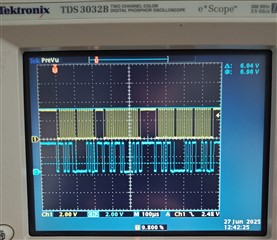
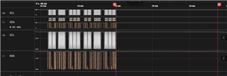
      This resulted in the error state;

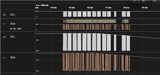
      This resulted in normal operation
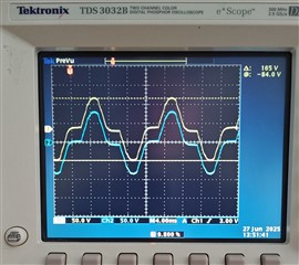
    According to the logic analyzer, power decays about 68 us sooner in the first picture compared to the second picture.

    This product has about 67 uF of capacitance on VIN which is probably why this transaction can occur at all. I expect that the PMIC has interrupted the MCU just before this transaction is initiated, and then the MCU asks the PMIC for its status. The amount of time between VIN being disconnected and the power decaying is dependent on the state of charge of the VIN capacitance.

    The next picture shows the case where ONLY the battery is connected and the "ship-it" I2C transaction (disable watchdog then disable BATEFT) occurs. The power always begins to decay well after the completion of the BATFET disable transaction, and in this case the time is 2.72 ms after completion of the transaction. So it seems that the safest method of placing the PMIC into the shipping mode, in my case, is to first disconnect VIN and then send the shipping I2C transaction.

  • Hi Anthony,

    Based on your captures I would agree that entering ship mode with VIN not present is a safer method due to the unavoidable I2C transactions that take place when SYS is already losing voltage. It appears that the I2C transaction is done much quicker than any loss in voltage.

    Alternatively increasing SYS capacitance so the voltage will take longer to decay, sufficient for the I2C transactions to complete, may be a solution. Though this would take some characterization to find the right capacitance value.

    Best Regards,

    Juan Ospina