This thread has been locked.

If you have a related question, please click the "Ask a related question" button in the top right corner. The newly created question will be automatically linked to this question.

UCD3138A: question about UCD3138A

Part Number: UCD3138A
Other Parts Discussed in Thread: UCD3138

Tool/software:

Hello:

The application issues for customer UCD3138A are as follows:
The application is a constant current source project, and during debugging, it was found that there was a sudden change in the DPWM cycle. The following experiments were conducted to address this phenomenon:
The program runs in an open loop, and in the first experiment, it was verified using the demo board of TI. It was found that this cycle is stable, but does not match the calculated value. The cycle set to 16000 should correspond to a cycle of 4us, but the measured value is 4.045us, which is 45ns larger than the calculated value,
The second experiment, also an open-loop operation, was tested on the customer's own board, and a sudden cycle change occurred again. The phenomenon is that every 3 to 4 cycles larger than the theoretical value, a cycle of two durations of 4us suddenly appears;

The customer's question is, is it reasonable for the actual cycle to differ too much from the theoretical value? How to avoid the phenomenon of the second cycle jump?

This has always been a problem in previous applications, but most of the previous projects were constant voltage source projects, which did not require high output voltage ripple and did not affect usage, so we did not pay attention to this situation. The recent constant current source project has very high requirements for output current ripple, and even the smaller the current ripple, the better. When the customer measured the ripple, they found that there was an irregular jitter in the current ripple under open-loop conditions. Therefore, it was traced that the period given by UCD3138A was fluctuating.
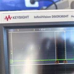
The first picture below shows a strict cycle of 4us, and the duration of the next cycle increases by about 20ns


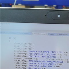
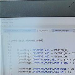
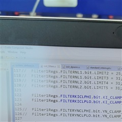
The power stage is not working, only UCD3138A is operating in open-loop mode, which has little to do with the peripheral circuit. The customer thinks there may be a problem with the software settings and wants to seek help from TI's technical support to investigate this situation.

  • Hello Jimmy,

    An offset of 4ns would correspond to 1 PCLK of the UCD3138A (PCLK is a 250MHz timer). So, 4ns or 8ns delay/shift from the intended event would be an expected offset due to the oscillator/processor timing (Ex. if you try to sync 2 DPWMs together, often they may be 4ns apart due to it taking 1 PCLK cycle to sync). 45 ns, however, is quite a large difference that should not be caused by the UCD3138A itself. For 45ns offset to occur, I think something should be wrong with your code and the timings you set. 

    Do you have any programmable deadtime in the code? Any fault, CBC or blanking times? Any clamping between the front end sensing and the DPWM event? Any interrupts? These could all be potential sources of delay.

    FYI, July 4th is a US holiday. Please expect a delay in further responses.

    Regards,

    Jonathan Wong

  • Hello Jonathan:

    The current application is fixed dead zone and open-loop operation, fault,CBC,blanking time, There should be no clamping or interruption, and the customer also believes that it should be related to software settings or peripheral circuits. Does TI recommend a demo program for reference?
    Additionally, there are actually two issues on the customer's end,
    1. In the demo board test of ti, the cycle is stable, but it is about 45ns larger than the set value
    2. Testing the same program on the customer's own board, the cycle begins to abruptly change, but the same cycle as the set value can be measured.

  • Hello Jimmy,

    If the issue is related to software settings, then I would need to view the code to see if there are any issues. We do have existing UCD3138 firmware that I would recommend as a starting point as well as a way to compare if your settings are correct. They can also start with the UCD3138x training labs, which configure the UCD3138x in an open loop configuration in Lab 2. What topology is the customer using? 

    By "fixed dead zone" do you mean fixed dead time? 

    Regards,

    Jonathan Wong

  • Hello Jonathan:

    Yes,ucd3138 is worked on open loop mode, fixed deat time,frone_end,filters,are not work,and only dpwm0 is enabled.My customer‘s project is base on HSFB Frimware-1.1, but the code already changed too much .

    Customer set the code run to idle state then turn on dpwm and stoped,here is code.

  • Hello Jimmy,

    Thanks for confirming that their starting point was the HSFB EVM firmware. Can you please share the actual code instead of pictures? The pictures also do not really show much of the code. After all, the 3rd picture only shows commented out code and the code that is not commented out I cannot see what the KI_CLAMPs are equal to.

    As a note, you can insert code in E2E by going to Insert --> Code and selecting C in the dropdown.

    if(1)
    {
        clear_filter0;
        clear_filter1;
        clear_filter2;
        LoopMuxRegs.DPWMMUX.bit.DPWM0_FILTER_SEL = 0;
        Filter0Regs.FILTERCTRL.bit.KI_STALL = 0;
        Filter1Regs.FILTERCTRL.bit.KI_STALL = 0;
        restart_counter = 0;
        FeCtrl0Regs.RAMPDACEND.bit.RAMP_DAC_VALUE = 93
        FeCtrl0Regs.EADCDAC.bit.DAC_VALUE = 9300;
        FeCtrl0Regs.DACSTEP.bit.DAC_STEP = 100;
        Fault_flag.bit.vout_ov = 0;
        
    void init_dpwm0(void)
    
    {
        Dpwm0Regs.DPWMPRD.all = PERIOD_H;
        Dpwm0Regs.DPWMEV1.all = EVENT1_H + DT;
        Dpwm0Regs.DPWMEV3.all = EVENT1_H;
        Dpwm0Regs.DPWMCYCADJB.all = DT1_H + D
        Dpwm0Regs.DPWMCTRL0.bit.PWM_B_INV = 1;
        
        Dpwm0Regs.DPWMCTRL0.bit.PWM_MODE = 2;
        Dpwm0Regs.DPWMCTRL0.bit.CLA_EN = 1;

    Below are some more questions:

    • What is the deadtime and DPWM period value? 
    • What DPWM mode are you using? Why is DPWM EVENT2 and EVENT 4 not defined?
    • Is only DPWM0 enabled or are other DPWMx signals enabled?
    • Are there any syncing between blocks? (Ex. is DPWM1 synced to DPWM0)
    • You said the operation is open loop. However, the first picture shows that the Front End is initialized for a ramp. Is this Front End ramp being used? What is the input to the filters?

    Regards,

    Jonathan Wong

  • Hello Jonathan:

    The customer feedback on the questions you asked has the answers in the pictures provided above,
    Among them:
    PERIOD_H=16000,
    EVENT1_H is 132*4
    DT1_H is 90*4,
    DT2_H is 40*4.
    As for the value of KI_CLAMP, it does not work here

    Please help check,Thanks!!!

  • Hello Jimmy,

    I will continue to look into this issue and provide a response tomorrow.

    Regards,

    Jonathan Wong