Other Parts Discussed in Thread: BQ25756EVM, , BQ25756
Tool/software:
Hello,
I want to use the TPS26750EVM as a sink to charge a battery, either in standalone/PPS mode or by combining it with BQ25756EVM. After going through the TPS26750EVM user guide (which I personally found it to be a bit confusing due to version errors/mismatch), I have come up with the following configurations which can be used to charge a battery, can you tell me which one is correct or in any of them are correct at all?
1. Dead battery safe mode / Dead battery always enable sink mode -
Config 1 -
- Connect a 140W USB charger to J3 to power the board
- Connect another 140W USB charger (which is the main charger with which I will be charging my battery) to J4
- Access power output from J7 which will then go to the battery/BQ25756EVM board
Config 2 -
- Connect a 140W USB charger to J4
- Use the same charger to charge the battery by accessing power output from J7 which will then go to the battery/BQ25756EVM board
The reason behind my confusion - The user guide description given on page 10 implies config 1 whereas figure 2.4 and 2.5 imply config 2 (as per my understanding)
Which one of the above configurations is correct?
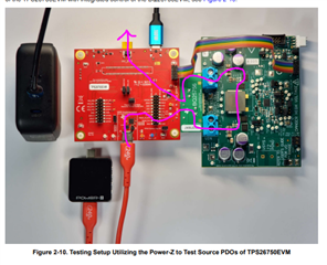
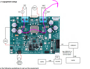
2. TPS26750EVM and BQ25756EVM -
How do we connect both these boards and use the combination as a sink to charge a battery?
A statement on page 13 says - "To source and sink power in the EPR range using the TPS26750EVM, users want connect a simulated battery to
the HV_SYS header (J8) instead of powering the board through J3."
Again as per my understanding -
- Connect a 140W USB charger to J4
- Use the same charger to charge the battery by accessing power output from J8 which will then go to the battery
Is the above configuration/understanding correct? If the battery is connected to J8 then how are we using the BQ25756EVM board as a part of the sink?
3. Standalone testing mode -
- Connect a 140W USB charger to J3 to power the board
- Connect another 140W USB charger (which is the main charger with which I will be charging my battery) to J4
- Access power output from J7 which will then go to the battery/BQ25756EVM board
Is this configuration correct?
Best regards,
Dattatreya