This thread has been locked.

If you have a related question, please click the "Ask a related question" button in the top right corner. The newly created question will be automatically linked to this question.

BQ25798EVM: VSYS OVP FLAG and VBAT OVP FLAG

Part Number: BQ25798EVM
Other Parts Discussed in Thread: BQ25798

Tool/software:

Hi,

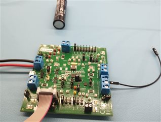
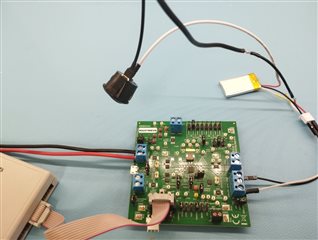
I am using the BQ25798EVM with this setup: 

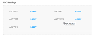
I configured it with 1 Cell but I am having the VBAT OVP FLAG tough ADC BAT measure is 3,853V.

I can't figure out why this is a problem.

Please see attached configuration/measures:

bug_bat_OVP.docx

  • Hi,

    What condition causes the VBAT_OVP? Are you enabling charge and then the OVP occurs? What is the voltage reading by multimeter on the pin TP29 - BAT?

    Best,
    Michael

  • Hi, 

    Yes, the error occurs when I enable the charge (JP17 plugged).

    When I remove JP17, the error disappears.

    When the error is up I have 4.00V on TP29 (same value between B+ and B-), which is the value read by the ADC.

    On TP28 (VSYS), I read the same thing than the EVM ADC : 4,6V

    BTW I do not understand why VBAT and VSYS are not the same...

  • Also D13 STAT LED blinks at approx. 1Hz meaning there is an issue..

  • Hi,

    Is there any battery protection device attached to the battery here?

    Best,
    Michael

  • Hi, good catch, there is indeed.

    I removed it and retried but same result.

    BTW I get the VBAT_OVP even when no battery is plugged (nothing is plugged at output..).

  • Hi,

    With the BQ25798, any floating state on the battery terminals will result in the VBAT_OVP. This can be from a battery protection device in a HIZ state, a missing battery, or other similar state. When you removed the battery protection, did you still have the battery cell on the terminals?

    Best,
    Michael

  • Hi,

    Yes, i tried with the battery without the protections.

    I sucessefully made it work by shortening the EVM/ battery wire length (I had a amperemeter between before).

    I do not understand why it doesn't work with long wire as there is not even much current (10mA...).

  • Hi Walter,

    When you say that there is not much current being 10 mA, this is lower than the charge current I remember seeing set on the TIChargerGUI screenshots. Is this correct? I had a similar issue when I took the EVM to the lab and used wires similar to the setup in the first picture. The output current was less than I expected because the output voltage seen on the EVM was high and reached the regulation point. I think that the wires are not just long, but also thin, which is making them high impedance.

    BTW I do not understand why VBAT and VSYS are not the same...

    Also, I just realized that I did not answer this question. VBAT and VSYS are not the same because VSYS is typically regulated at a higher voltage than VBAT, except while charging. While charging, the BATFET is fully on, and any impedance between VSYS and VBAT becomes a voltage drop dependent on the charge current.

    I am glad to hear that the battery is charging. Are there any other questions or issues I can assist with?

    Best regards,
    Michael

  • Hi Michael,

    Thanks for your feedback.

    One more question about VSYS charge termination voltage:

    Are those following the voltages on VSYS wen the charge is terminated ? 

    Does that mean that for instance, with a 1S cell, there is a small drop from 4.2V to (max 4.55V) on VSYS when the BATFET is turned OFF ?

  • Hi Thomas,

    Yes, this is correct. For the BQ25798, when charge has terminated, the device regulates the system voltage slightly above the battery voltage to avoid power being drawn from the battery through the body diode of the BATFET.

    The charging cycle reaches 4.2V on the battery and enters CV mode. When the current drops to the termination level, the BATFET turns off. After the BATFET is off, the system voltage is increased to ensure there is no current through the BATFET.

    Best,
    Michael

  • Hi Michael,

    Ok, well noted.

    I still don't quite undertand why too long cables (even big ones) triggers an OVP warning, even when charge is almost terminated and there is little current so not much voltage drop..

    In that case should I recommend my client (he'll decide the cable length) not to use too long cables ?

    Also, it is not clear what value is VSYS when the charger is in OVP mode ?

  • Hi Thomas,

    The long cables could cause an OVP if there is a fast transient on SYS that requires supplement mode.  When the load is removed, the long cable could cause inductive voltage spike on BAT pin.  More capacitance on BAT or SYS pin prevents this.

    Charge OVP is not a charger state but a fault condition during which the converter turns off.  The intent is to give the SYS load a chance to discharge the battery below the OVP threshold (105%*VREG).  VSYS is not regulated during this time because the battery FET is turn on to connect SYS to BAT.

    Regards,

    Jeff