This thread has been locked.

If you have a related question, please click the "Ask a related question" button in the top right corner. The newly created question will be automatically linked to this question.

UCC24612: Synchronous Rectification

Part Number: UCC24612

Tool/software:

Hello Team,

We are designing a LLC converter with 55V Vout and 3A output current.

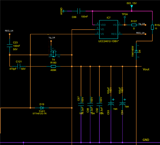
We are planning to use Synchronous Rectification at the output of LLC Half bridge, the reverse voltage across MOSFET will be 135V approx.

I've attached a snip of half of the secondary side with UCC24612 driving a MOSFET, other half of the secondary center-tap is the exact replica of this. 

Both half of secondary sync. rectifier ICs' have seperate isolated 15V supply.

We just need to confirm the connections and whether the IC can be used for our desired voltage ratings.

Or else you can suggest us with any other better solution as well.

Thanking you,

Regards, 

Dilip Ramgir 

  • Where is the transformer center tab?

    R152 will consume a lot of power between 55V Vout and 15V supply.

  • Hello Dilip, 

    In addition to Ning's concern about R152 power loss, there are other issues as well: 

    1.  C66 and C23 values should be in uF's not in nF's.  See datasheet examples and recommendations. 
    2.  VDD cap C66 should terminate to VS pin 2 of IC7 (close to the IC), not to some "AGND". 
    3.  REF cap C23 is should also terminate to VS close to the IC, not remotely at the MOSFET source, as shown in the snippet. 
    4.  Also, the return net of the ISO_15V output should terminate to the VS pin. 
    5.  Given the ISO_15V source for IC7, why is there any need for R152 and D4?
    6.  With 135V max across T4, a 50V-rated C121 snubber cap will not last long. 
    7.  499kR value for snubber R180 makes the snubber useless, unless this is just a placeholder value to be adjusted later.  Make sure the resistor is sized appropriately for the power loss. 

    Regards,
    Ulrich