This thread has been locked.

If you have a related question, please click the "Ask a related question" button in the top right corner. The newly created question will be automatically linked to this question.

BQ76952: BQ76952 charging and discharging power flow

Part Number: BQ76952
Other Parts Discussed in Thread: BQ76972

Tool/software:

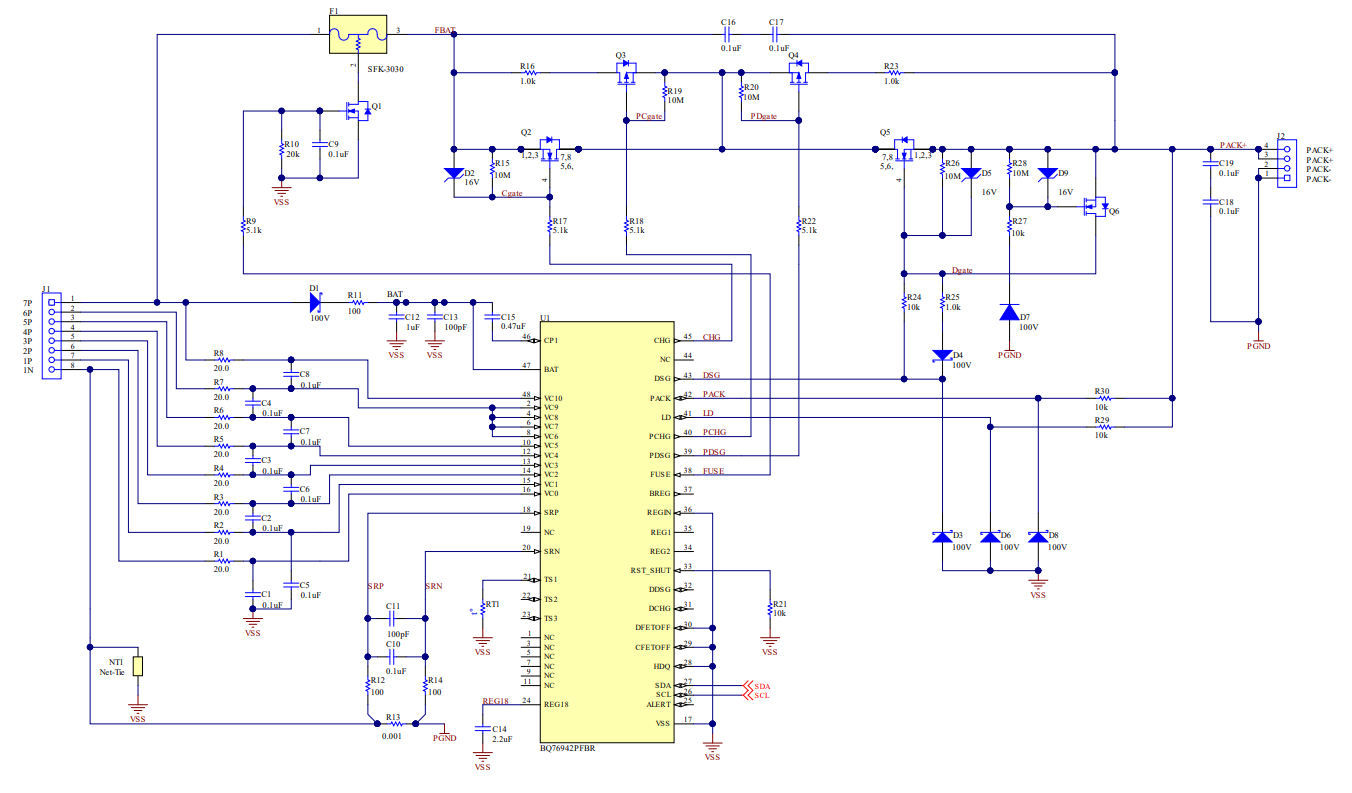
Here attached reference schematic from TI datasheet.

I am planning to use first time BQ76972 BMS IC, therefore, i want to understand power control flow of charging and discharging From battery to Load and Load to battery.

when CHG MOSFET and DSG MOSFET will operate (Q2, Q3,Q4,Q5, Q6).

I request to TI team to explain in a simple.

  • Hello Kaushik,

    Q2 and Q5 are our charge and discharge FETs. There are many different triggers for these FETs. Settings:Protection:CHG FET Protections or Settings:Protection:CHG FET Protections can help give a sense of the variety of protections that can enable each FET. These can all be configured. Examples of protections include overvoltage, undervoltage, and diode protection. Based on what protection is triggered, the discharge FET might turn on/off or the charge FET might turn on/off. For more details on the variety of protections that might trigger the CHG and DSG FETs, I would recommend taking a look at section 5.1 of the TRM.

    Q3 and Q4 are our precharge and discharge FETs. The precharge FET is used to reduce the charging current for an undervoltage battery. The PCHG FET will be used for charging when the voltage has dropped below the precharge start voltage that you can configure. The predischarge FET is used to reduce current when the load is initially powered. For more details on the purpose and configuration of the FETs, I would recommend viewing Section 5.2.3.2 of the TRM.

    Q6 is our reverse charge FET. This is a protection in a case where an incorrect charger is attached, which would cause the battery and charger to push current in the same direction. In this scenario, when pack+ is pulled below VSS, Q6 will pull the Q5 gate to its source keeping the discharge FET off. For my details about the reverse charge circuit, section 2 of the Multiple FETs app note may help.

    Another resource that might help is our battery management video series.

    Let me know if you have any further questions or if anything is unclear.

    Regards,
    Rohin Nair