Other Parts Discussed in Thread: BQ79718V-Q1,
Tool/software:
Hello,
I'm trying to set correctly GPIO configuration on BQ79718V-Q1 mounted my PCB design. For now I use BQ79600EVM to write/read commands to/from the cell monitor.
This is the configuration that I need:
- GPIO0 as RX
- GPIO1 as TX
- GPIO2 as NFAULT
- GPIO3, GPIO4, GPIO5, GPIO6 and GPIO11 as ADC input
- GPIO8, GPIO9 and GPIO10 not used
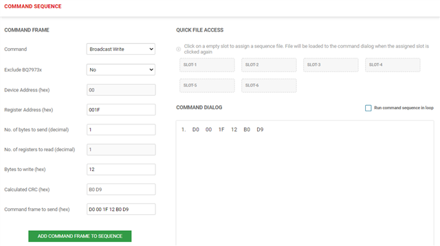
Using the information from datasheet I build my command sequence. Only GPIO3 and GPIO4 as an example:
Init (broadcast write of 1 byte): 1101 0000b or 0xD0
Device address (address device 0): 0x00
Register address (GPIO3 and GPIO4 is set with GPIO_CONF2): 0x01F
Data (GPIO3 and GPIO4 set as ADC input absolute): 0001 0010b or 0x12
Seems frame should be:
- D0 00 1F 12
I'm not sure about how many bytes I should use for the address. DS tells two so maybe the correct frame is:
- D0 00 00 1F 12
Which frame will be accepted on the BQ79718?
Thanks