This thread has been locked.

If you have a related question, please click the "Ask a related question" button in the top right corner. The newly created question will be automatically linked to this question.

TPSM53603: Schematic confirmation for 12v to 36v input supply and output 6v and current 3A

Part Number: TPSM53603

Tool/software:

TPSM53603RDAR_inputsupply_ajay.pdf

Hello there,

I hope you doing great, if not you will be, 

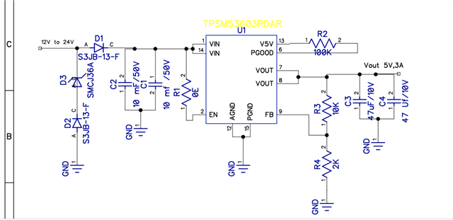
May you please confirm if added schematic will work, 

Input supply 12v to 36v

Input current can go upto 15A,

Required Output parameters:

6V, 3Amp current

Will the given schematic work for this output parameters. and if reduce the value of R4 to 1.65 then will i get 7v also with same setup

second thing, does really need to be short with 100k Resistor or we can skip that part

Third ,we connected D1,D2 and D3, Where D1 and D2 is Schottky diode for reverse current flow stoppage and D3 is TVS diode for Transient voltage protection, does D1 and D2 really required for TPSM??

Thanks for your time:-)

  • Hi,

    My comments regarding the schematic :

    1) D2 should be removed for the transient voltage protection to work properly. D1 is optional but good to have, for cases when VOUT can go higher than VIN, such as startup with a pre-bias. If such conditions are not expected you can remove D1 also.

    2) You will need some smaller ceramic capacitors also at the input (~20 uF at least). The current 10 mF capacitors are too large to be effective at higher frequencies, so from the perspective of the buck they do not provide much use. If they are not needed for any preceding devices you can remove them. 

    Connecting PGOOD to V5V through the 100k is optional. It is only needed if you want power good indication functionality. Otherwise you can leave it open.

    Yes, if R4 is reduced to 1.65k you can get 7V output with same setup.

    Regards,

    Niranjan

  • Thanks Niranjan for your kind reply,

    I am still bit confused about the input capacitors, do i remove the two 10mF /50v(As suggested by TI datasheet) and add single 20mF ceremic capacitors or i will add A C-case 233mF big single capacitor at input end?? please do tell me any other advice related to capacitors or any side of TPSM.

    This IC will working 24/7 in Vehicls(Bus or Trucks) high frequency current from input supply(vehicle batteries) may be expected.

    Thanks for PGOOD and V5V suggestion, i get it.

    Thanks & regards

    Gurditta Singh

  • Hi Gurditta,

    The datasheet recommends two 10 uF capacitors, not 10 mF. You can use that value.

    One other thing is, if the input trace is long its parasitic impedance can cause ringing at the input. To damp this, you might need an additional high ESR electrolytic cap (in the range of 100s of uFs)

    Using capacitors in the mF range will not be useful as they might not be very effective at high frequencies.

    Regards,

    Niranjan

  • Thankyou, It was a mistake, I was using micro Farad by indent was wrongly set(mF). 

    Thanks again for your help Niranjan.

    Have a lovely day ahead:-)