Other Parts Discussed in Thread: BQ27427
Tool/software:
Hello team,
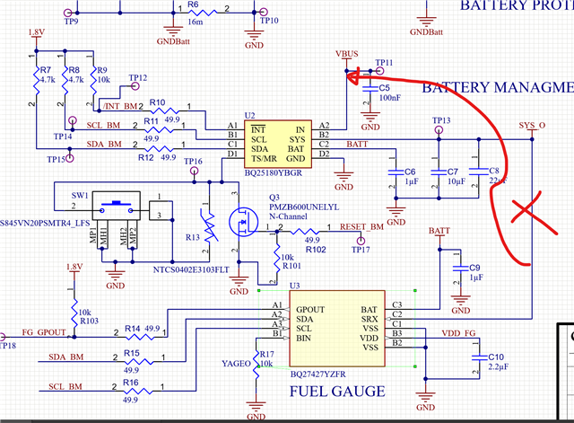
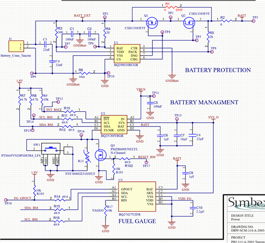
I've been working with the BQ25180YBGR, but I can't set the reset button to make VSYS low. I've tried to condigure the VSYS according to the datasheet, using the SYS bits, and also using the reset input, but it doesn't work, so, I would like a double check on the schematic. I've removed Q3 just incase that it is making some problems, but the behavior is the same. This is the schematic that I have for the battery managment.
This is the final configuration that I've used
reg 3 = 0x46,
reg 4 = 0x2F,
reg 5 = 0x30,
reg 6 = 0x56,
reg 7 = 0xC4,
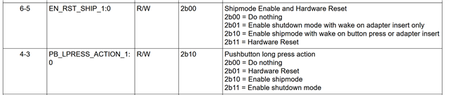
reg 8 = 0b00011011,
reg 9 = 0b01101101,
reg 10 = 0b00101100,
reg 11 = 0x00,
reg 12 = 0xc0
This is the test result. I can see a try on VSYS, but it doesn't go low.
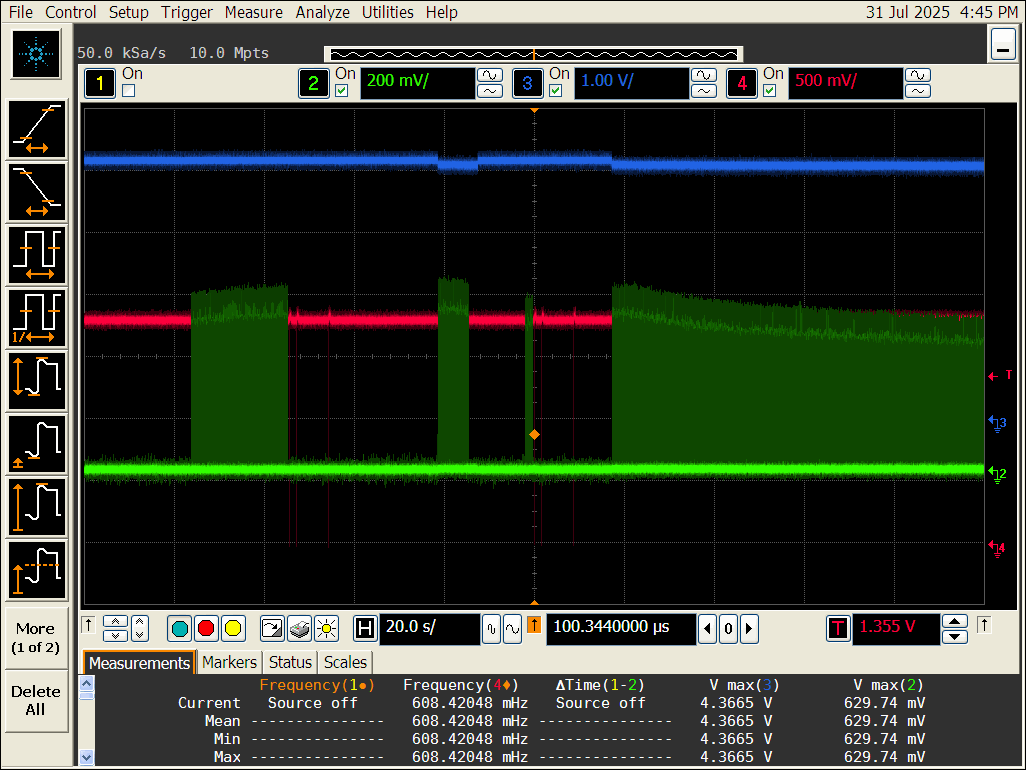
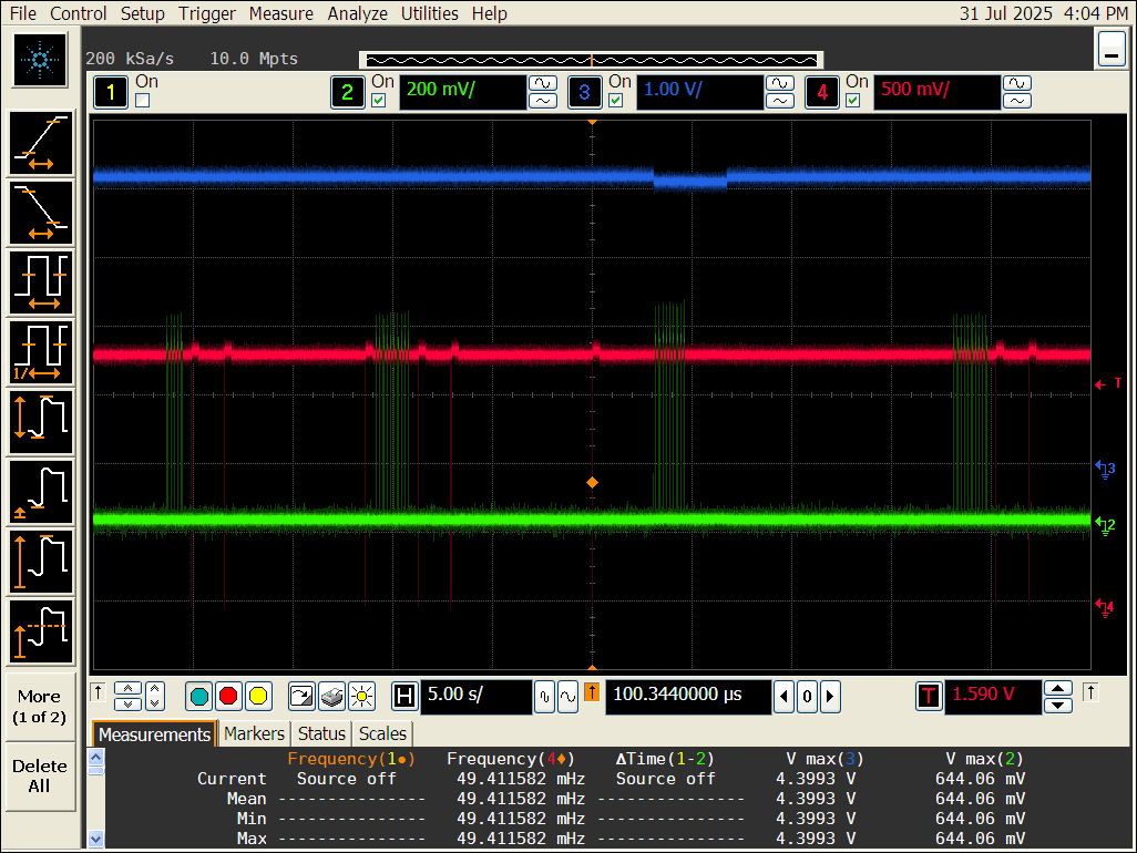
Please, let me know if you have an idea. I've seen the test result on the datasheet and seems that It whould work.
Regards
Francisco