This thread has been locked.

If you have a related question, please click the "Ask a related question" button in the top right corner. The newly created question will be automatically linked to this question.

LM5101: LM5101A

Part Number: LM5101
Other Parts Discussed in Thread: TINA-TI, , SM74104, , PSPICE-FOR-TI

Tool/software:

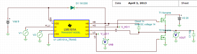
I am unable to find LM510A model among the libraries given in TINA Spice under Spice Macros.

I am using this part to drive the NMOS output switches for an H-bridge driver configuration.

  • Hello Subhajit,

    I did find the LM5101A Pspice models and TINA-TI models in the link below in the LM5101A product page, under design tools and simulation.

    https://www.ti.com/product/LM5101A?keyMatch=LM5101A&tisearch=universal_search&usecase=GPN-ALT#design-tools-simulation

    Regards,

  • Thanks a lot Richard.

    I was able to download the transient model test-bench but unable to get it to work. I have modified it to configure as a half-bridge driver driving 2 NMOS 2n6755 transistors. A diode 1N1200 is connected across VDD and HB & a cap of 10n across HB and HS. VDD=5V and the high voltage HV connecting to the drain of upper NMOS is 20V. I have applied complementary 5V amplitude 1 MHz square wave inputs to HI and LI. The output is stuck at 9.2 V. So is VHO. VLO is almost ground. 

    (I would also like to try SM74104 also if that is a better circuit for H-bridge & capacitive load.).

  • Hello Subhajit,

    In looking at your response I see that VDD was set at 5V, please confirm. The LM5101 driver VDD UVLO is above 5V so the part is likely in UVLO. The recommended VDD range is 9V to 14V. Can you try a higher VDD of 10V. Will the higher VDD work in your application?

    I looked at the SM74104 datasheet and i see that it is a single control input driver with adjustable dead time. It also has a VDD recommended range of 9V to 14V.

    Regards,

  • Yes, that was the issue. However, I am still not getting the proper levels at the output. With VDD=10V, HI and LI still at 5V amplitude I am getting 29.7 high level and 9.9V low level at the output whereas my high voltage battery is at 20V. A VDD of 9V is OK altho' I would prefer a 5V VDD (same as my input levels).

    I also noticed that the Spice Level-3 models of all the MOSFETs in the library are the same. Not sure if I am using the right MOSFET model.

    SM74104 does not have a TINA transient model but a PSPICE Transient model. Can it be imported into TINA Spice or do I have to download the PSPICE-FOR-TI simulator (which is not an issue) ? Does PSPICE-FOR-TI simulator support all parts of TI ? Is it preferred over TINA-SPICE.

    Thanks a lot.

  • Hello Subhajit,

    Can you provide a picture of the schematic that you are simulating, I am curious if the HS pin is switching to ground to charge the HB-HS capacitor in your simulation circuit. Also in your sim results can you confirm the HB-HS differential voltage and the HO-HS differential voltage when HI is high.

    Regards,

  • The schematic is attached. The circuit seems to work with a proper NMOS transistor model. I changed the model to Spice-Level-1 with parameters Vt=1V, kp=2m, gamma=0.5, phi=0.6. The output is switching from 0 to 20V as expected and the bootstrap cap seems to be getting charged as expected.

    With a single input and dead-time adjustment I would like to switch over to SM74104. I would like know if I can import the PS{ICE Transient model available into TINA Spice. Or do I have to download PSPICE-FOR-TI simulator for this.

    Regards.