Tool/software:
This will be an additional question.
When using the MPQ5850 made by another company, MPS, with the power supply connected in reverse,(Fig.1)
a problem occurred in which the power supply on the load side was turned on via the GND=>FET=>SW path (Figure 1).
This is because the correct potential is generated between the power supply's FG and the load's "+".
The cause of the problem with the MPQ5850 can be identified using the equivalent circuit, but not with the TPS26631PWPR equivalent circuit.
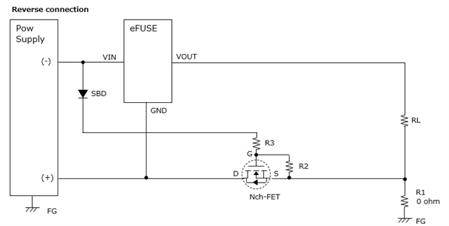
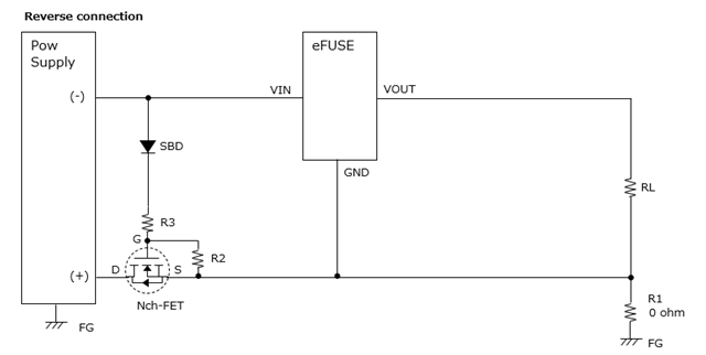
Q1.Does the TPS26631PWPR have such a current path? (Fig.2)
Q2.Does the FET have a diode so there is a path for current to flow? (Fig.2 Route2)
*The datasheet states that the MPQ5850 also has reverse polarity protection.
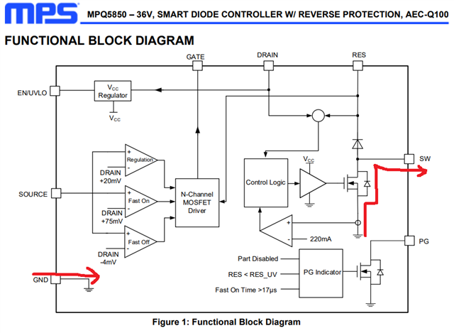
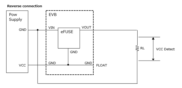
Fig.1
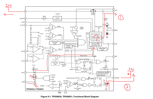
Fig.2