TPSI3052-Q1: 89MHz EMI issue

Part Number: TPSI3052-Q1
Other Parts Discussed in Thread: TPSI3052, TPSI3100

Tool/software:

Hi team, 

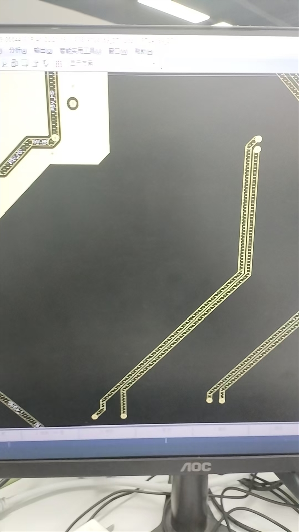
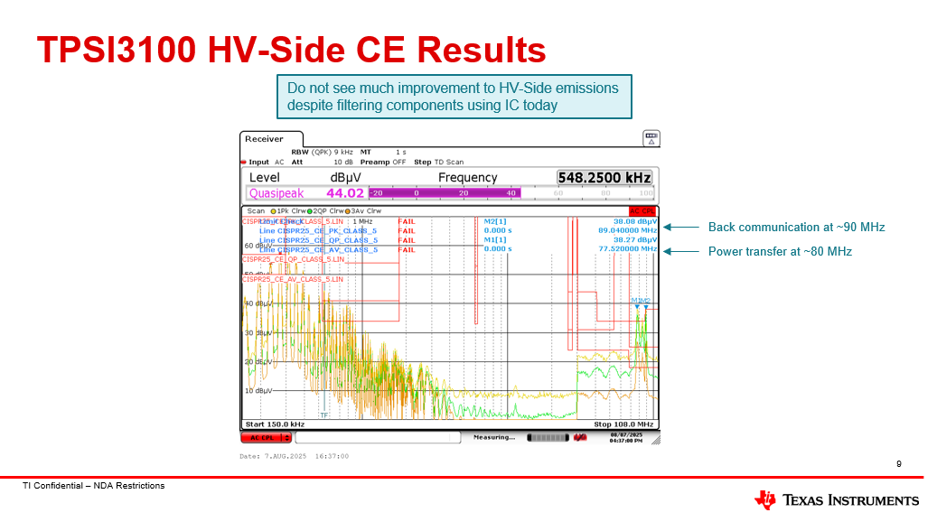
My customer is using TPSI3052 in OCB product and met 89MHz EMI issue.

In datasheet, we see 89MHz is used for iso barriers communication.

Do you have any solution that can solve this EMI issue?

  • Hello Gary,

    Thanks for reaching out to our team on E2E. Can you please share more details on the layout? Looking at the schematic, I recommend a few things:

    1. Remove C395
      1. Y-capacitance in our own testing seems to make 90 MHz noise worse.
    2. Reduce R537 to 7.32 kΩ.
      1. This reduces power transfer, would affect start-up time and maximum switching frequency.
    3. Add input filtering
      1. If L24 is not populated, try installing BLM21HE802SH1L onto R683 and R684
      2. If BLM21HE802SH1L does not fit, try installing DLW32SH101XF2L onto L24 
    4. Add output filtering
      1. Try installing BLM21HE802SH1L in L25.

    Best regards, 
    Tilden Chen


    Solid State Relays | Applications Engineer

  • Hi Tilden,

    Customer change resistor from 20kohm to 7.32kohm. But it still has EMI issue.

    Add layouts as below:

  • Hello Gary,

    Thanks for your support.

    Today, TPSI31xx can pass low-voltage-side emissions (CISPR25 Class 5) testing using BLM21HE802SH1L. However, we have been unable to pass high-voltage-side emissions testing (CISPR25 Class 5), so if your customer is testing high-voltage-side emissions next, we do not have a solution. Our team is working to redesign the TPSI31xx for improving emissions, targeting to have samples available 1Q25.

    Best regards, 
    Tilden Chen


    Solid State Relays | Applications Engineer

  • Hi Gary, 

    Happy to help further reduce any EMI the customer is seeing. Can you begin by confirming: 

    • Is 89MHz EMI issue is from the primary or secondary side emissions?
    • Were ferrite beads populated as discussed in Tilden’s recommendations below, or only power transfer reduced by change resistor from 20kohm to 7.32kohm

    In total, here are our EMI recommendations for the TPSI3XXX family: 

    1. Adding ferrite bead (FB) placeholders
      1. I recommend something like the BLM21HE802SH1L for its high impedance around 80MHz
      2. TPSI31P1 operates with fundamental frequency at 80 MHz, these FBs showed best performance for reducing noise here
      3. please ensure there is no ground plane underneath the ferrite beads on other layers. 
    2. Reducing 5V plane into a trace
      1. Since the power level is low (milliamps), trace should be sufficient at DC. However, transiently the TPSI3100 will be pulling current at 80 MHz so we need to worry about power plane behaving as antenna in EMI.
    3. Adding stitching capacitance between device primary and secondary grounds
      1. This is overlapping planes on different layers to create capacitance in-between. Stitching capacitance creates a low impedance path for high frequency (common-mode) noise to return. 
    4. Adding 10 nF 0402 input/decoupling capacitor to TPSI31P1
      1. SRF around 80 MHz (helps differential-mode noise)
      2. Place this one as close as possible to pins 3 and 4 

    We are also addressing EMI from a silicon standpoint, with our release of TPSI3100A (samples Q1) which will have an improved EMI performance to the current TPSI3XXX families. 

    Best Regards, 

    Elizabeth