This thread has been locked.

If you have a related question, please click the "Ask a related question" button in the top right corner. The newly created question will be automatically linked to this question.

TPS51116: 1.8V DDR2 not starting up all the time.

Part Number: TPS51116


Tool/software:

Hi Team,

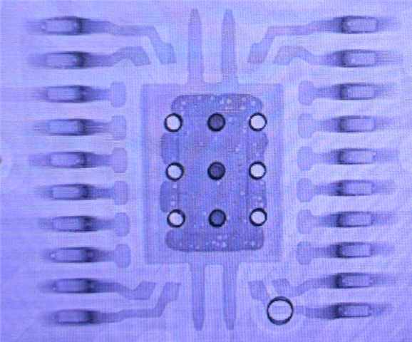
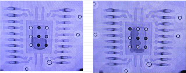
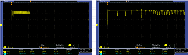
TPS51116 circuit we have been using for several years has begun to not start up on many PCBs. Sometimes just changing the part will make it work and sometimes not. Looking closer at the circuit it appears that the low side MOSFET is not staying turned on. Below is the circuit.

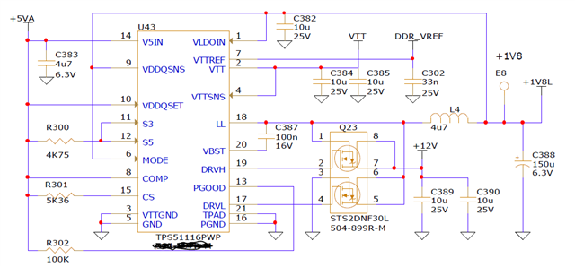
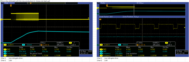
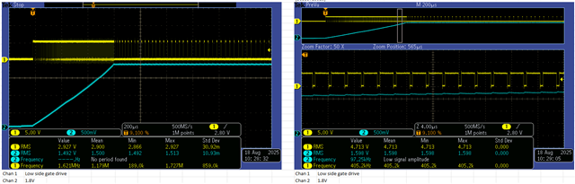
What we found was by lowering R301(CS pin) to 1.8K we can get some of them to fire up but not all of them will work. Below is the low side gate drive on a working one.


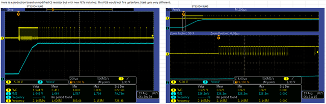
Here is one with the reduced resistor to 1.8K but it still won't start up.

We know the low side gate drive is being turned off but we are not sure why.

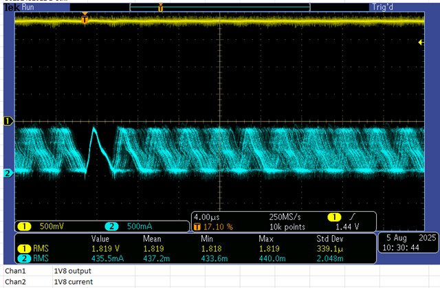
The output current measured on a good working is ~435mA. Below is current after inductor with scope current clamp.

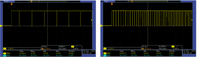
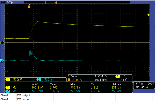
Here is good one starting up.

Here is bad one.

Also I had a bad CS resistor read ~300K and it fired up all the time. Some original value 5.36K fire up but not all of them.Then we switched to 1.8K and again some of them fired up but not all.

We tried this on 10 PCB's. There is something strange about this value.  Would you have any ideas of where else to look in this circuit to help us resolve this issue.

Thanks,

Mike

  • Hi Mike,

    Can you try increasing the CS resistor just to see if something like 10k increases the number of working boards? Based on the statements above, there seems to be a CS resistor dependency so I would like to start there.

    What have been the main changes since this circuit has been working for a long time? How is the system different from past inventory where all the ICs are working?

    Regards,

    James

  • Hi James,

    I can try the 10K I'll have to get approval and let you know how it works out.

    We haven't changed anything, we checked date codes on TPS and DDR2 ram everything is good. We spent lots of time looking for something different and could find nothing.

    Changing value of CS resistor. Basically I put a 10K pot in parallel with 5.36K and tweeked it till it worked. We came up with 1.8K and it worked on a few boards but does not seem to be the root cause.

    Thank you,

    Mike

  • Hi Mike,

    Another form of testing that could be valuable depending on resources would be an A-B-A swap with two units (one working, one failing) just to confirm if this issue follows the ICs or the board.

    I'm not sure what to suggest if this design has been working for years up to this point and then suddenly boards are no longer working. The fact that only some boards fail and others continue to work with this design is also a confounding point since I would expect a systematic issue to manifest on all boards.

    You mentioned data codes. Is there a specific date cutoff where these DDR2 modules begin to show issues? Or are even previously working older modules now struggling? I'm just trying to understand the timeline of when/how this issue first cropped up a bit more.

    Regards,

    James

  • Hi James,

    I'm going to try the A-B. With working to non working That's great idea. I should of thought of it.

    Digging deeper about what has changed.

    I found an old PCB that works great

    Good PCB's soldering from 2022.

    Here are some the failed PCB's solder, less than 50%.

    Would poor solder affect the circuit operation besides thermal? Were only pulling 1.8V X .435mA = 783mW.

    Thanks,

    Mike

  • Hi Mike,

    According to the datasheet the minimum recommended solder coverage area is 78% so both those failed units seem to have insufficient soldering on the thermal pad.

    If there's a GND reference or connection issue with the part, it could cause issue with regulation or reference circuits. Even if it's not the root cause of this particular issue, it's something I would bring up to your manufacturing contact.

    This is another point that can be checked using the A-B-A swap since since you might be able to rectify the bad solder job after swapping both parts. There are 3 outcomes that I would expect:

    • Issue follows the IC (unlikely since these are very robust parts and I haven't seen this issue anywhere else) - although we can't rule it out yet
    • Issue follows the board - more likely since we've already seen some slight correlation with the CS pin resistor
    • Issue disappears on both boards after swap - I could see this happening if it turns out to be a thermal pad soldering issue as the re-solder might fix the issue on both boards.

    Regards,

    James

  • Hi James,

    I swapped IC's and now my old PCB does not work and the new production PCB works with the old 2022 IC?

    Can you tell us anything about the DC?

    Old IC that's working markings

    TPS51116

    78T

    C3NR

    New IC not working marking

    TPS51116

    1AT

    CLG1

    Here is old production PCB with new IC.now not working

    Note at end of start up the frequency of lower MOFET gate drive is 2.2Mhz.

    Here is new production PCB with old IC. Works every time.

    Note frequency at end of start up is  409 Khz

    It followed the IC? Both have 5.36K CS like original design.

    Thanks for your help,

    Mike

  • Hi Mike,

    We could still see if the 10k changes anything in the hope for a board level fix to account for some variation these units might have.

    Let me just check internally if there's any lot history information that can be easily looked up on this.

    Regards,

    James

  • Hi Mike,

    For the failing units you can initiate a CPR as well since it looks like the issue follows the ICs.

    www.ti.com/.../customer-returns.html

    Regards,

    James

  • Hi James,

    The guys want to play around with the FETs for awhile I thought I would show you some results. They don't want to CPR as the card is almost EOL and we need to get a pile out. But if this don't work we might have to.

    Here's one that would not fire up with original 5.36K CS. Not ideal. The newer FET was all we changed.

    Here's another FET we tried. This also would not fire up with 1.8K CS. Also not ideal.

    I'll chime in next week after a pile of testing to let you know how we made out.

    I guess you could not find anything on the date codes from the devices. I could not find anything on the data sheet.

    Really appreciate your help with this one.

    Thanks,

    Mike

  • Hi Mike,

    So I understand, were the FETs changed before this issue popped up or were you still using the same FETs from the 2022 design and the issue still appeared?

    Regards,

    James

  • Hi James,

    We were always using the same FETs STS2DNF30L. We decided to change them for a test this week as we are using the RDSon current limit scheme.

    The resuls are not that great as you can see. We see 2Mhz in the start up burst before 1.8V levels out. But at least the supply started up.

    Thank you,

    Mike

  • Hi Mike,

    Understood. One other resource we have is our TPS51116EVM. According to the BOM in the User's Guide, it looks like the FETs used for this are the IRF7821 for HSFET and IRF7832 for the LSFET (Infineon)

    Unfortunately both of these FETs seem to be obsolete now but the specifications might be worth checking to compare.

    Regards,

    James

  • We changed them after we found this issue to see if it would help. The original FETs were the best.

  • Hi James,

    The issue followed the IC on several boards.I can't figure out the date codes. We found a band aid to get us through.

    Main issue was 2Mhz in the start up burst. Now it's gone as you can see.

    Thanks for your help. You can close this.

    Mike

  • Hi Mike,

    Got it, and what was the band-aid? Just a sweet-spot resistance on the CS pin?

    Just want to note it for the record here.

    Regards,

    James

  • Hi James,

    It was to put 68 ohm load on 1.8v output and more local decoupling on +5 input side of R302. The HF is gone.

    RC snubber at L4 input works to but hard to implement on PCB.

    Thanks for your help.

    You can close it.

    GL,

    Mike.