LM5155: Double switching pulse in flyback boost converter

Part Number: LM5155

Tool/software:

Dear TI Team,

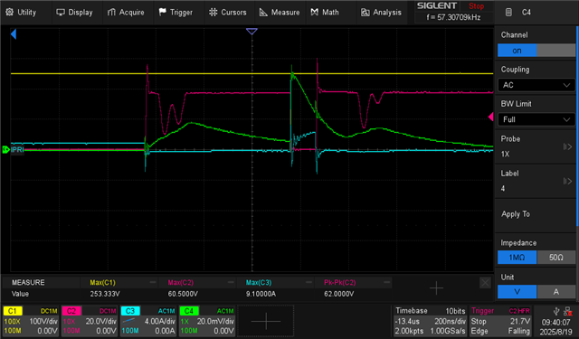
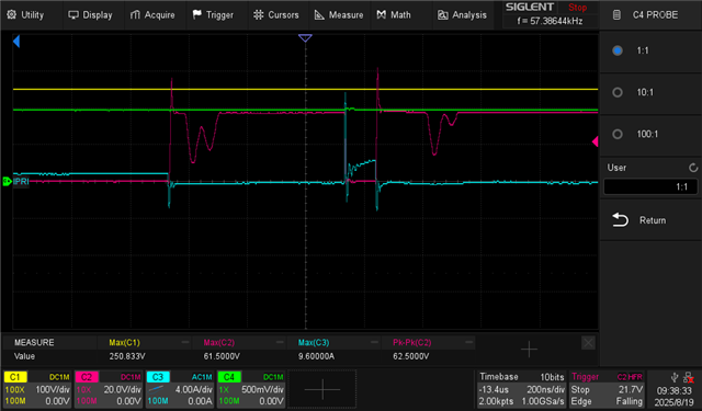
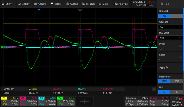
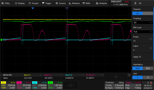
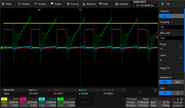
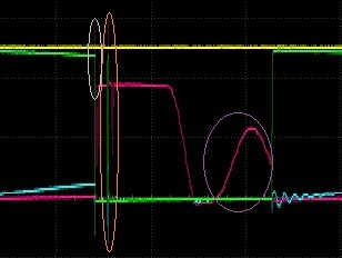
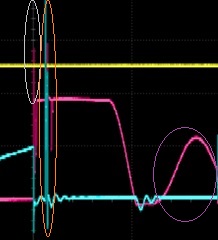
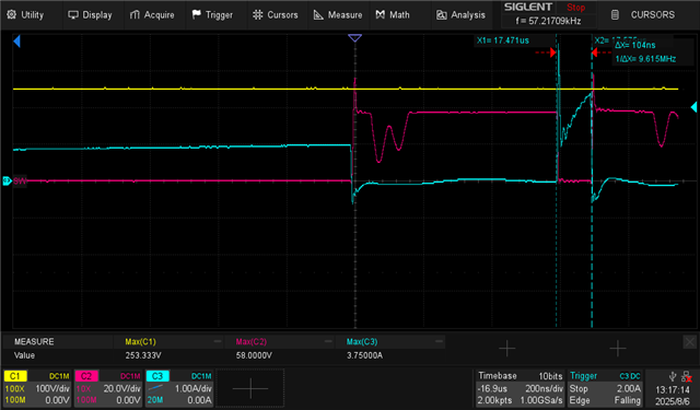
Do you have any advice on how to eliminate this double switching pulse? These are measured waveforms using a custom board and BNC probe contacts: output voltage (yellow channel), switch node voltage (magenta), primary current measured across current sense resistor (cyan).


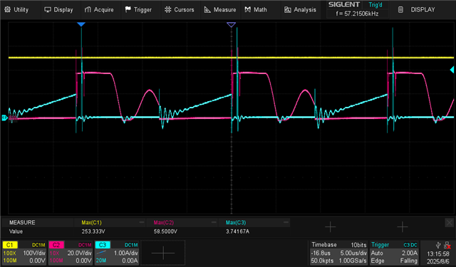
Shortly after the FET stops conducting, the controller turns the FET back on for about 100ns.

If someone wants to reach out to me, I can share schematic and quick start calculator, etc.

  • Hi Daniel, 

    I am assigning this question to our experts. As there is a public holiday on 15th August, 2025. Please expect the earliest reply by next week. Thank you so much for your patience and understanding.

    Best regards,

    Mounika

  • Thank you Mounika, have a good holiday.

  • Hi Daniel,

    According to the waveforms, it seems like that your converter is entering into over current protection. You can see that the measured current has a spike.

    Can you please measure the CS signal with small ground loop connection along with the gate, SW node, FB, COMP signals?

    Best Regards,

    Hassan  

  • Can you please attach the schematic of your design as well? Thanks

  • Hi Hassan,

    Thanks for reaching out.

    I have BNC test points for:

    SW NODE  (Magenta/Red)

    VOUT  (Yellow)

    Current (FET) (Blue)

    These waveforms are visible in all screenshots.

    Then in green you see the following pin being probed with a ground spring on the scope probe.

    FB PIN

    COMP PIN


    CS PIN

    GATE

    I will send you the other information via PM now.

    Thanks for taking a look!

  • Hello Dan,

    Thanks for the screenshots.

    Your images show a lot of parasitic distortions.

    To clarify the wording upfront:
    When you say "double switching pulse", you are talking about the signals in the orange circle (green, red and blue spikes)
    and not about the red signal inside the purple circle.
    Is that correct?

    The red signal in the purple circle is regular normal, parasitic ringing in DCM, when the energy is fully consumed.


    But there are multiple heavy parasitic distortions in the system.

    - The inductor current has quite some ripple.
    - Right when the FET turns off, there is one big overshoot inside the gray circle. This is not nice but not too dangerous.
    - Short afterwards, in the orange circle, the FET turns on again (for a short while). Switch node voltage and inductor current show a big spike. This could really damage the FET and other components.


    Please try the following improvements:

    - Introduce a gate resistor between 3 and 10 Ohms
    - Implement a snubber (RC device) across the FET
    - Reduce the (parasitic) inductance of the sense resistor (different vendor, different shape of the component)
    - Use a different (slower) FET
    - If nothing else helps, minimize the parasitics of the layout, especially the path from the FET to GND, to avoid gate shifts.


    Best regards
    Harry

  • Hello Harry,

    Thanks so much for all the advice! I don't know if you have access to the schematic? I sent that to Hassan in a private message.

    Yes, I am referring to the brief pulse, not the ringing that is typical with flybacks.

    Here is a zoom in on that region.

    I have an RCD snubber from switch node to Vin (typical) and can add a snubber across the FET too.

    But from what you said, I think I need to re-visit the BOM. I am using a very fast FET (~2ns !) I will replace that with something much slower.

    Thanks!

  • Hello Dan,

    You are right, such fast FETs will usually cause this kind of issues.
    Maybe you can save the snubber and the gate resistor in that case.

    Thanks
    Harry

  • Dear Harry and Hassan,

    I have added an RC snubber across the FET (I think there is more I can do here to turn the values).

    100 Ohm gate resistor

    The rise time is somewhere around 50ns-100ns using 100 Ohms

    and the second turn on still occurs


    1k Ohm gate resistor

    I picked an extreme value of 1k gate resistor; this gives a turn-on of around 1us,

    The second turn on is still there!

    RC snubber on rectifier diode

    I thought to add an RC snubber across the rectifier diode on the secondary side, this helped with the ringing in the current waveform.

    But still the double switching pulse remains.

    Final recommendation?

    Is it reasonable to strongly suspect the layout? I mean, it's in your interest to suggest it's the layout so I go away, but I'm honestly curious Slight smile if you can think of anything else. I can share gerbers if interested.

    Thanks for the help so far.

    PS. Updated with RC snubber on rectifier rather than adding to the post.

  • Hello Dan,

    Can I assume that the green signal is the gate of the FET?
    This would confirm that the gate signal is not driven by the controller and that there is a heavy ground shift.

    Also, I wonder why the inductor current is oscillating that much.
    Maybe you do not have enough CERAMIC capacity or very long and thin wires between power supply and PCB.
    All GND connections of the power path, especially from the FET through the sense resistor to GND, but also all the others, must be VERY solid and short.
    Also, do not use any thermal relief connections for the power stage.

    A 1k gate resistor is way too high and must not be used (I understand that it was just an experiment).
    I would also consider 100 Ohm as much too high.

    So, I would recommend - as per your own proposal - using a much slower FET.
    Your switching frequency is anyway pretty low.

    Best regards
    Harry

  • Can I assume that the green signal is the gate of the FET?
    This would confirm that the gate signal is not driven by the controller and that there is a heavy ground shift.

    Yes, in the first three images of my last post the green trace is the gate.

    I need to probe that by hand; in the last two images I was not probing the gate -- so it looks like it is now active but it is was.

    Thank you very much for the advice!