LM5143A-Q1: LM5143A-Q1 2-Phase Buck Converter – Lead-Acid Battery Connection and Charging

Part Number: LM5143A-Q1
Other Parts Discussed in Thread: LM5143-Q1

Tool/software:

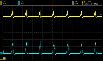
We are testing a two-phase synchronous buck converter (25 V input, 15 V output) with no load. A 12 V lead-acid battery is connected at Vout. When the switch is turned ON, the waveform shows overcurrent protection is triggered.

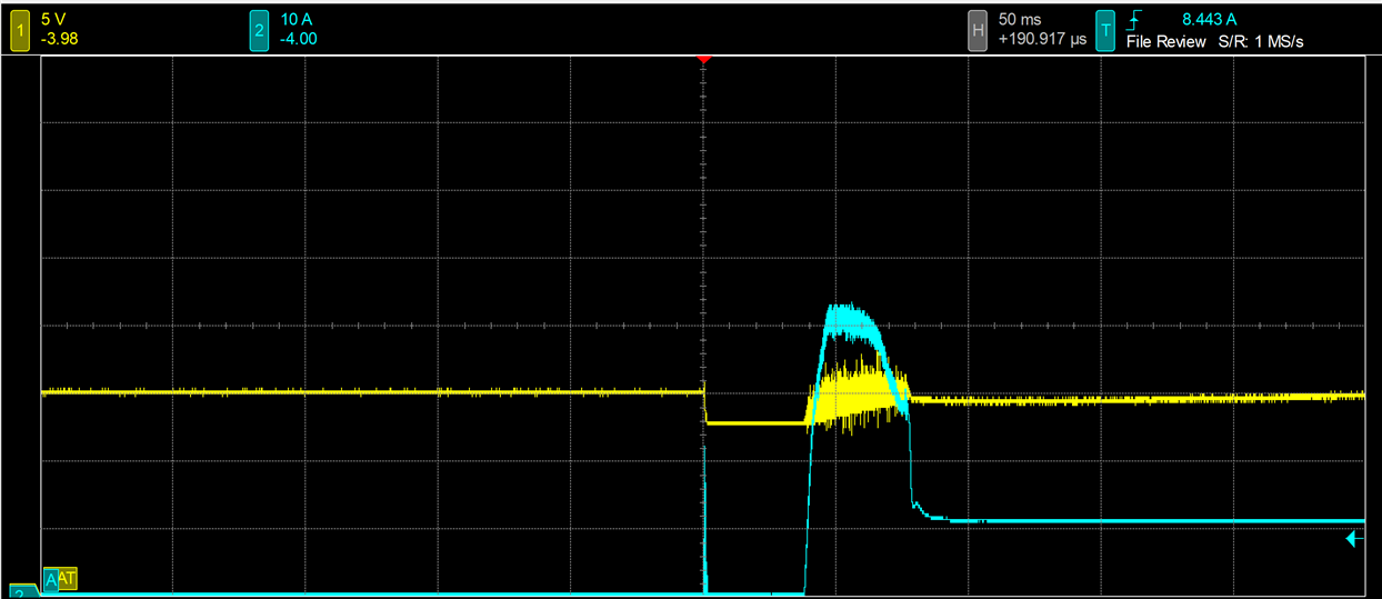
Furthermore, We attempted to short the overcurrent protection feedback voltage, thereby disabling the overcurrent protection function, in order to confirm whether the observed issue is caused by excessive charging current. Turning ON the switch while Vout is regulating at 15 V causes a high voltage and current surge (waveform not captured), resulting in LM5143A-Q1 failure.

In addition, we need to use the 15 V output to charge a 12 V lead-acid battery. Could you advise on the proper way to implement this safely, or any recommended precautions to avoid damaging the IC?

Any guidance would be greatly appreciated.

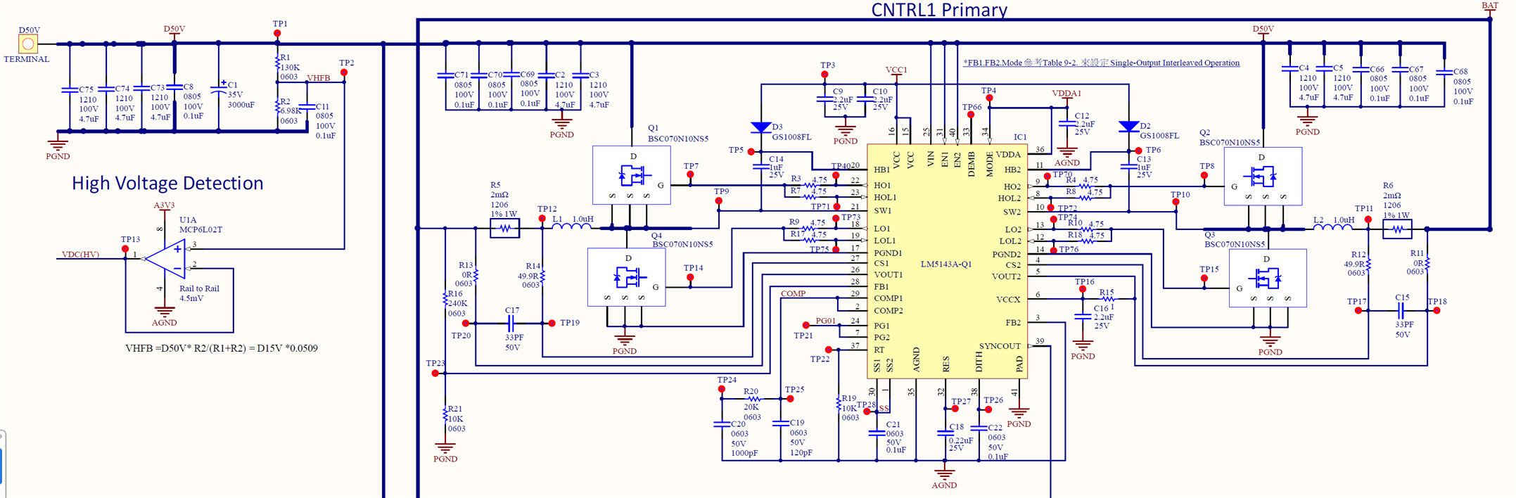
The following shows the current LM5143-Q1 Quickstart Design configuration for your reference.

https://docs.google.com/spreadsheets/d/10v15ki_UtsdKey5BotfdEzC5Y4a5UaL6/edit?usp=sharing&ouid=104433332549816947365&rtpof=true&sd=true

Best regards,

YUMING

  • Hello YUMING

    Could please share direct xcel supported QuickStart, as we do not have access to google drive?

    For this device, you will need signal level FETs which supports 5V gate drive, check with FETs with plate around 2-3V


    Thank you

    Regards

    Onkar Bhakare

  • Hi Onkar:

        Apologies for the oversight in our previous update. The MOSFET has been changed to ISC0805NSL, which features a lower VGS(th).

    At present, we have adjusted the SS pin capacitor to 2.2 µF, which allows us to directly connect a 12 V lead-acid battery for charging. 

    We need to perform a test where the 12 V lead-acid battery and a 5 A load are momentarily disconnected and then reconnected (hot-plug). This produces a large surge current. We currently place a 35 V TVS at VOUT for suppression. Our target test is the same hot-plug with the 12 V battery and a 35 A load. In our trials, the higher the load current, the larger the transient/inrush current at VOUT.
    Do you have any recommendations?

    LM(2)5143-Q1 quickstart design.pdf

  • Hello Yun

    You will need a CC-CV implementation to charge the battery. Check the following app note - How to Implement a Simple Constant Current Regulation Scheme to a PCM Based Buck

    Without CC loop either you will hit the current limit or if you try disabling it by it would lead damage of FETs and power stage.

    Thank you

    Regards

    Onkar Bhakare 

  • Hi Onkar:   

    Thank you for your reply. We will review this and appreciate your guidance.

    Based on the document you provided, the example connects both the CV and CC circuits to the same FB pin. If the target output voltage is 15 V, the FB pin will feed back 0.6 V to the LM5143A-Q1, which will operate in CV mode. In this case, would the CC circuit still function as intended? Could you please advise?

    Additionally, could the LM5143A-Q1 be configured to provide both constant current (CC) and constant voltage (CV) outputs simultaneously? We would greatly appreciate any guidance or recommended approach for achieving this functionality.

    Thank you very much for your support.

    Regards

    YUMING

  • Hello Yuming

    I'm currently out of office. I'll get back on this in day or 2