Other Parts Discussed in Thread: TPS62065-Q1
Tool/software:
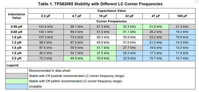
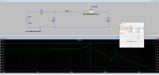
1. 1uH & total 20μF capacitor is placed at the buck output of the TPS62067-Q1, and a filter combination of a ferrite bead + 22μF capacitor is respectively placed at each of the three load terminals. Now, please help analyze whether the tested Bode plot indicates stability. Is it necessary to reduce the capacitors at the load terminals to ensure the total capacitance does not exceed 47μF when using CFF compensation?
2.If a two-stage filtering scheme of "ferrite bead + capacitor" is adopted near the load end at the post-stage, what specifications of the ferrite bead and capacitor need to be considered in the design to ensure the stability of the power supply?
3. Additionally, since the current circuit consistently operates in the light-load mode (around 100mA), resulting in large voltage ripple. If i want to replace it with the TPS62065-Q1 (configured to FPWM mode), apart from adjusting the Mode pin configuration according to the datasheet, are there any differences in other external components design?