BQ27220: SRP and SRN connection

Part Number: BQ27220

Tool/software:

Hi everyone,

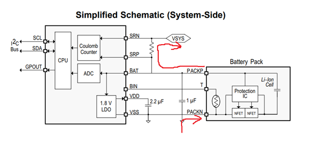
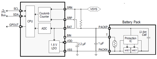
I have just been assigned to an ongoing design that uses a BQ27220 fuel gauge and I was wondering if the proposed connections were right or not. I happened to find an old thread that stated that the following schematic is wrong, since SRP and SRN connections are swaped and thus the fuel gauge would see battery discharge as charging and viceversa:

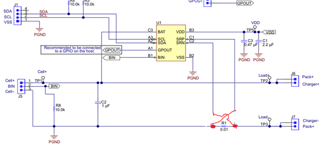
Considering the correct connections for SRP ans SRN (that would be SRN connected to Cell- and SRP to Charger-) I have one further question: would it be OK to connect GND to Charger- instead of Cell-? GND would be the overall device GND, so all other IC, including the BQ27220 and the charger of the device, would use it as GND connection.

Thanks in advance

  • Hello,

    This question has been assigned and will be followed up when possible.

    Thank you,
    Alan

  • Dear Alan, please let me know if there is any update regarding my question.

    Thank you.

  • The connections in red are incorrect. A discharge current flows from cell+ to J6, enters the application/load connected to J6, returns to the EVM on J7 and then flows through the sense resistor R1, creating a voltage drop over this resistor. The upper end of this must be connected to SRP (which would have been the original blue traces) and the lower end to SRN. Check out the datasheet (which has a high side setup on the front page). The discharge current "hits" SRP first. It's the same on the low side.

    Discharge current:

  • Thank you for your answer. I have another question: the last image shows a high side connection whereas the image I attached in my first question showed a low side connection. I understand both are functionally equal, but is there any case where we should use one over the other?

  • It doesn't matter for the gauge if it's low or high side. It's usually required by customers, e.g. based on their protector.

  • Understood, thank you. One more question: considering the high side connection, the current that flows into the BAT pin is not considered by the gauge and thus would underestimate the discharge current and overestimate the charge current. I assume this is the pin the gauge uses for powering itself, so the current should be in the uA or tens of uA range. However, this could be a problem if the discharge current is for example 100 uA, right? I am assuming the chip does not internally measuring its own consumption and correct for it.

    I was wondering if connecting the Rsense like this would be a possibility since then it would measure the real battery current but the problem here is that the BAT pin would not read the actual battery voltage but rather the battery voltage minus the voltage drop across Rsense. The voltage difference would probably not be greater than +-50mV but I do not know if this effect could be worse than the current error produced with the previous circuit. 


  • The gauge's current can be compensated with "electronic load", see www.ti.com/.../sluubd4a.pdf 1.1.8 Battery Electronic Load Compensation.

    It's usually better to keep the battery measurement accurate and let the gauge miss the current that it consumes itself (because that current is often negligible vs. system load).

  • Thank you for you prompt response, we will look into it.

    Regards