TPS53355: Question of TPS53355DQPR current

Part Number: TPS53355

Tool/software:

Hi 

   We had used TPS53355 to power our 3.3V load.We found that our output current limit is too low,it just 4A,and we set current limit is set to 30A. Our load max current is 20A.

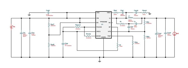
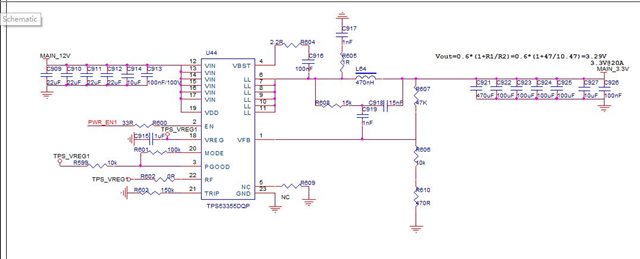
Our SCH is below,Our SCH copy by used TI WEBENCH to build SCH

We do some test and discovered some phenomena.

1.We had set different mode to test,we had set FCCM mode and auto skip mode,but the current limit is the same,it just 4A.

2.We also set current limt resistor,we set TRIP resistor to 300k and 510k,but the current limit is the same,it just 4A.

3.We had set Switching frequency,it works! When we set  Switching frequency is 250kHz,the current limit is up to 18A,but other Switching frequency even 300kHz,the current limit just 4A.

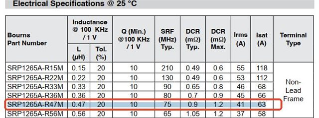
Our Inductance is SRP1265A-R47M , SRF is 75MHz

This phenomenon is very strange, what is the reason? How to solve it? We want the power to output 20A current.

  • Hello,

    The main points that affect current limit:

    • Trip Resistor
    • Double Check Mode resistor and RF resistor
    • Inductor rating
    • Double check Setup, if there is any current limit on input etc
    • Confirm that the design is the recommended design with recommended components

    Please confirm if these have all been verified.

    Please let me know and I can double check design and schematic on my side if I see any issues.

    Thank you,

    Calan

  • Hi Calan,

                We used WEBENCH build SCH is below

    Our SCH is below

    1.Our Trip Resistor is 150kΩ,I saw recommended design Trip Resistor is 137kΩ, Calculations show that the current limiting we set is greater than that of the reference design.

    2.We try all mode and all Switching frequency,When we set Switching frequency is 250kHz,the current limit is up to 18A,but other Switching frequency even 300kHz,the current limit just 4A.

    3.Our Inductor Parameter is below,we found that Inductor is OK

    4.Our input is from a regulated power supply, and we set the output of the regulated power supply to 12V/10A, which can output a total of 120W.

    5.The key parameters are copied from the reference design.And  Trip Resistor is larger that recommended design,Inductor we can not found 440nH,we found 470nH to replace it.And Rr we don have 18.7k ,we used 15k to repalce it, and we also try to repalce it with 18k,but the phenomenon is the same as before.

  • Thank you for sharing

    Please allow me some time to look into this

    Thanks,

    Calan

  • Hi Calan,

              Our PCB is 6 Layers,other layer is GND

    TOP

    BOTTOM is some FB resistor and Loop adjustment component

  • Thank you for sharing.

    Will respond to this next week.

    Thanks,

    Calan

  • Hi,

    I was able to review your schematic. I noticed some minor adjustments that can be made.

    • To confirm, you are selecting 970kHz as you are tying 0ohm to Vreg for RF. Please ensure this is desired
    • Inductor should be ok
    • Rtrip should be ok as well. It is recommended to use 107kohm, but 150kohm should not be an issue
    • I noticed your FB resistors equal 3.463Vout. You can modify these to 10kohm on bottom and 47kohm on top
    • I noticed you do not have a 4.7uF capacitor on VDD. This is highly recommended. Please add a 4.7uF capacitor on VDD, and let me know the result

    I am adding the excel design calculator which I have briefly inputted your design. Please refer to this and make any needed adjustments. Please also refer to the next couple of tabs which have schematic and layout checklist. Main issue I noticed is VDD not having 4.7uF cap.

    TPS53355 12vin 3_3vout 20A.xlsx

    Please let me know result.

    Thank you,
    Calan

  • Hi Calan,

    1.Yes,We had try 0Ω or 1Ω RF resistor to set 970kHz,we tested Switching frequency is 970.87kHz,it's OK

    2.Yes,we produced 10 boards and all board phenomenon is the same. Our inductors are samples provided by the manufacturer.

    3.Yes,we also try different TRIP resistor,we set TRIP resistor to 300k and 510k,but the current limit is the same,it just 4A.

    4.We set 10kohm on bottom and 47kohm on top,we tested Voltage is 3.42V,but the current limit is the same,it just 4A.

    5.We placed a 10uF capacitor on VDD,see Our SCH C914,it's for VDD.And we also change to 4.7uF,but it can not work,the current limit is the same,it just 4A.